Thanks for the info guys. Maybe he should/could have another give away and we can write or submit an essay for it ![]()
I gotta get a hobby other than being a “lurker” ![]()
Sorry for the momentary thread hijack Andrew.
Well I’ve still been tinkering around, making some progress! It’s nice that the major stuff is done and it’s just down to some details now.
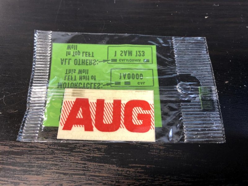
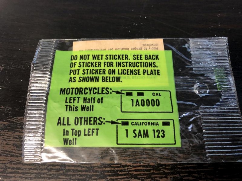
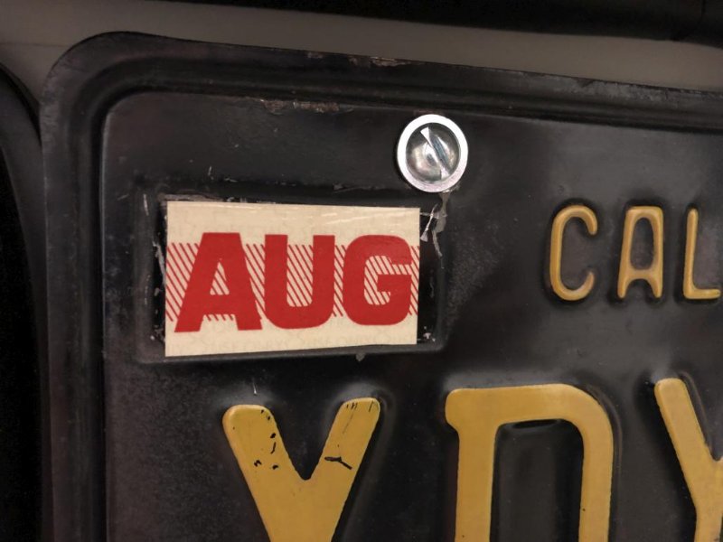
One fun thing is that I found a NOS month decal for my license plate. Thought it would be cool since I still have the original CA plates on it.
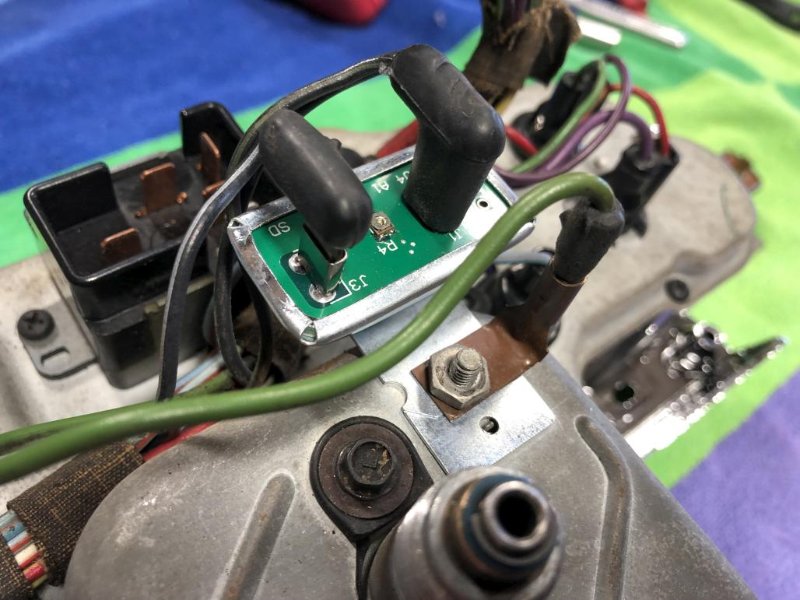
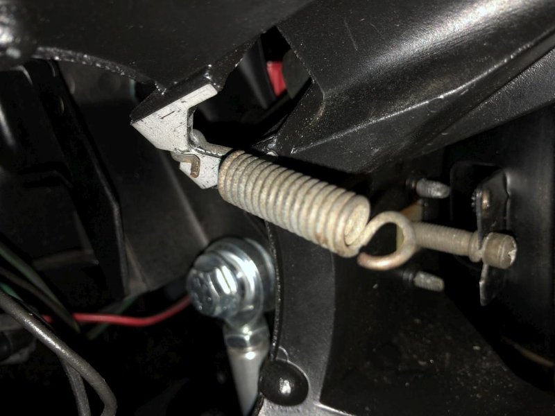
My next little adventure happened because I was trying to dial in the tuning and such. I went down a little bit of a rabbit hole to get the ignition system all happy. I’ve had a Pertronix Ignitor 1 in the distributor this whole time and it’s been working fine. But then I found out that it was only getting about 8V from the coil, because of the factory setup with the pink resistor wire. So doing some reading online led me to the conclusion that it would be better to get a full 12V to the Pertronix. So in order to do that, I switched to a Flamethrower coil which is designed for a full 12V, and embarked on a project to replace the resistor wire with a regular wire so the coil would get said 12V. So… I ended up popping the relevant pin out of the ignition switch plug, carefully opening up the pin, removing the resistor wire and running a new “normal” wire from that pin to the + side of the new coil. Kind of a pain but it was probably the cleanest way to do it.
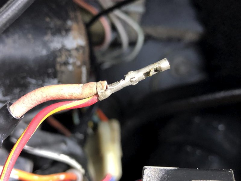
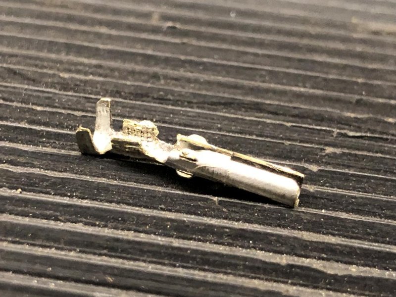
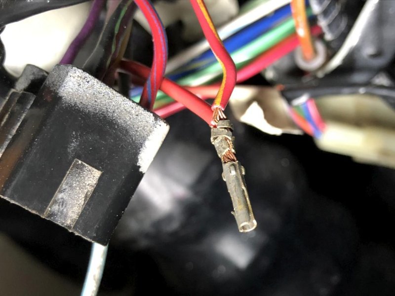
The above extreme closeup makes my crimp job look like crap. These wires and the pin are really pretty small and hard to handle. I stripped back a little extra on both wires to intertwine them so I think the contact is good. Once pushing the pin back into the plug there is no bare wire visible.
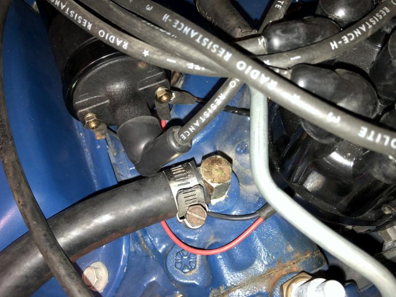
I had wrapped the new wire in black tape to make it blend in under the hood, then connected it to the coil + side, along with the Pertronix unit. Job done!
Anyway, so far this is all working out just fine. Though to be honest I’m not sure how much of a performance difference it made. I’m still chasing some timing and carb adjustments to really dial everything in.
On another note about ignition - as nice as the “concours” plug wires look, I don’t think they’re that great functionally. They’re hard to push all the way into the distributor posts, and when I was messing with the timing, I put my hand on top of the wires to turn the distributor and got shocked. Methinks that shouldn’t happen. So probably going to switch to boring plain black Pertronix 7mm plug wires.
More to come in a second post…
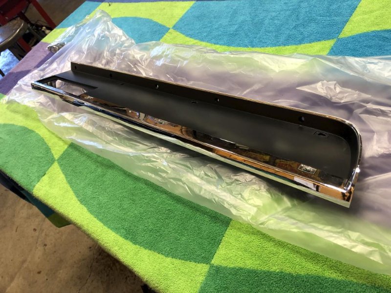
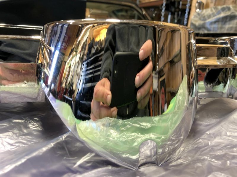
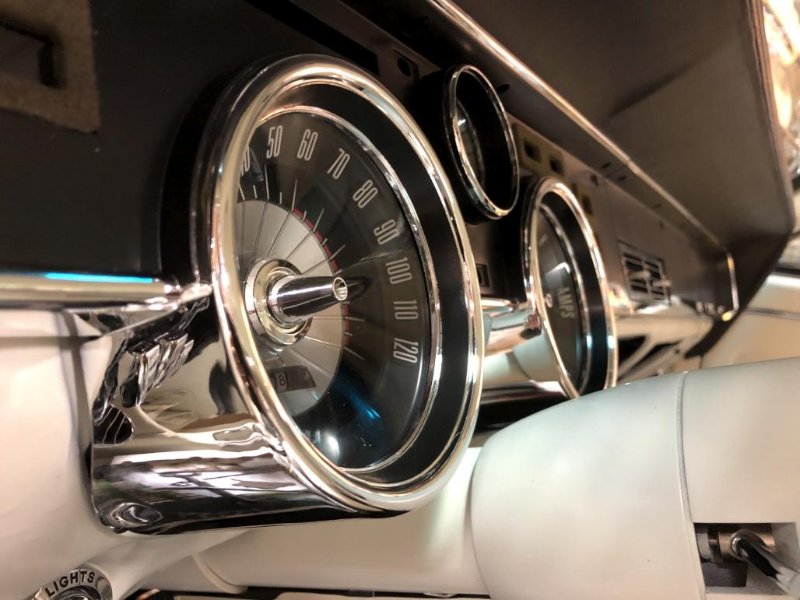
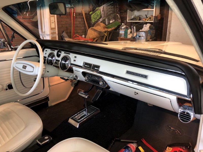
In fun shiny news, I got my vacuum plated dash pieces back from Vacuum Orna-Metal in MI. They turned out nice! Great mirror-like chrome shine. If this looks like deja-vu, it’s because I had previously installed some “spray chrome” pieces which were okay but not quite what I was going for. So out came the old and I got to re-assemble everything again. So shiny though…
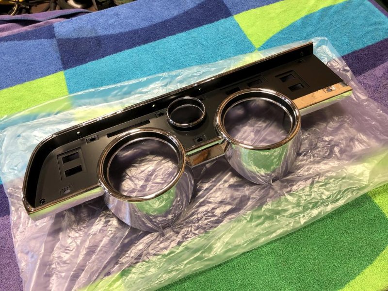
Gauges installed:
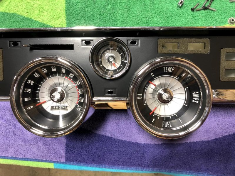
Annoyingly, the issues I’ve been having with the clock have persisted. When I test it on the bench, outside of the cluster, hooked up to a 12v power supply, it works fine and dandy. But once installed in the cluster, it doesn’t work at all. Must be some kind of mysterious ground problem. I ended up giving up and saying “I don’t need no stinkin’ clock anyway” and put my blank panel back in for now. But during the troubleshooting process, I barely tugged on one of the wires for an illumination bulb, and it pulled right out of the socket. So I ended up having to do a little repair to the wiring.
While I was in there I went ahead and installed a solid state instrument voltage regulator. Not because I needed it, but what the heck.
Anyway, after all that fiddling around I was ready to put the dash pieces in the car. They look great! Still a little torn on whether I should try to solve the clock issue since it is nice to have something there, but I wanted to move forward, so it’s just the blank plate for now.
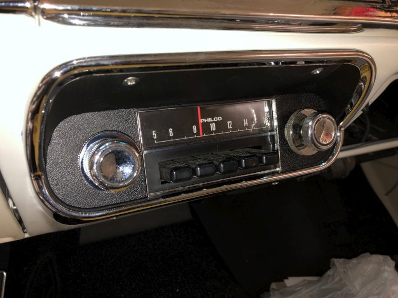
Then I could finally put my original AM radio in place (not working at the moment but it looks nice) with a new radio bezel and the hardware kit for it.
I also semi-repaired a crack on my dash face pad, in preparation for reinstalling it. More details of that are in a separate thread. Still haven’t installed, as I may be needing to pull the cluster out again…
FINALLY, by this point, it was a complete enough car to actually drive it home for the first time and get it out of Don’s way. The drive home went well, but I was on too much alert to really enjoy it. Driving in traffic for the first time I wanted to be sure the brakes were working right, and that it wasn’t going to stall, etc. But I made it home without issue.
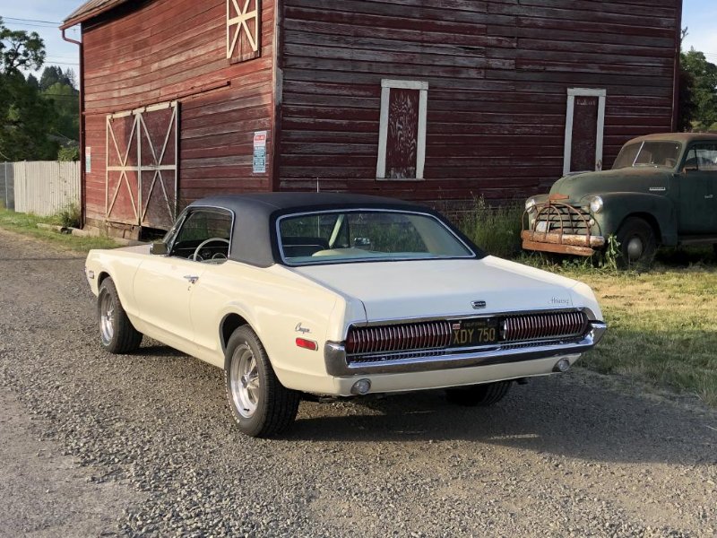
This past Saturday, it occurred to me that I could actually just take it out and drive it, for fun. What a concept! So I did just that, with the valid excuse that I needed to put in some shakedown time to discover any issues. And I did find some, but let’s start with some pictures out in the wild!
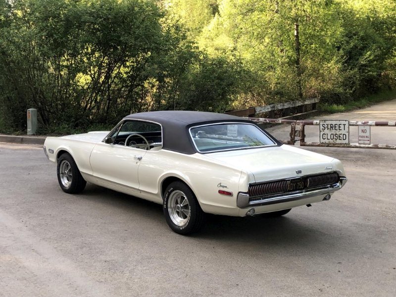
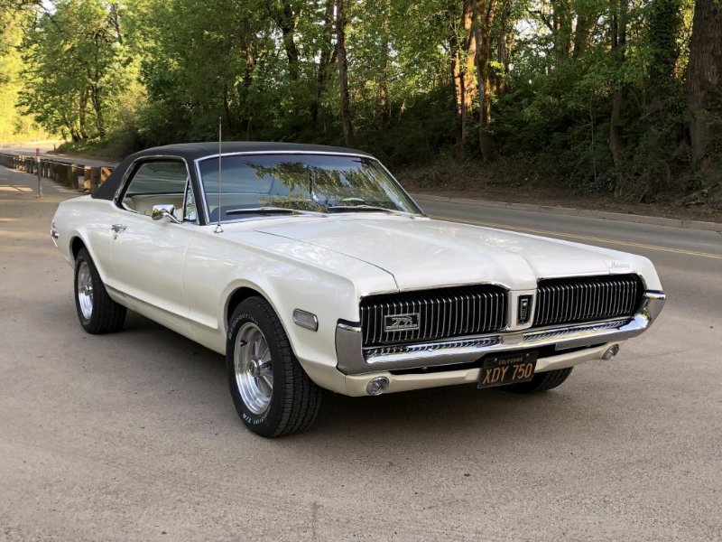
This time it was actually fun, because I was able to mostly relax and just drive. It felt good and reminded me of what I love about these cars. It just feels like a “real” car, something well built that has a strong and elegant presence that you just don’t get with modern cars. Piloting it around feels like a special occasion.
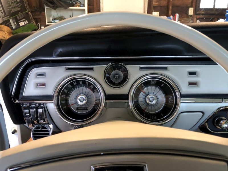
That said, some issues arose. Nothing that prevented me from getting back home, but take a look at this gauge.
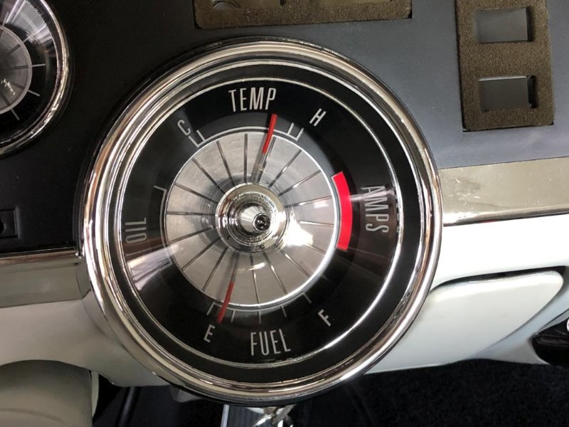
So nothing is good here, except I guess the oil pressure is ok. The AMPS light was intermittent and mostly very dim. So obviously some sort of charging problem. Alternator is nothing special, but it’s a new / reman unit from the auto parts store. That’s the obvious thing to check, but I suppose it could be a voltage regulator issue as well. Any tips on how to test that? My VR is also a new solid state unit (new several years ago anyway).
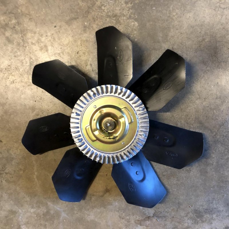
Temp was high the whole time, but I think I’ve figured that one out. After I parked, shut it down and it was still hot, I checked to see if I could spin the fan, or if the clutch was engaged as it should be. It span easily. So, time to buy a new fan clutch.
Next, the fuel gauge is wrong. I filled up the tank and it only read about 1/4 full. So that’s most likely a problem with the brand new stainless steel sending unit. Great! Richard, the WCCC electrical guru, suggested that it may not be grounding to the tank very well because it’s stainless. So I might try a test lead to see if running a dedicated ground wire does anything. Otherwise I’ll have to drive on blind faith for a bit until the gas gets low before I can pull the sending unit out and see what’s up.
Anyway, plenty of things to do still, but it’s gratifying to be at the stage where it’s actually a car that I can drive and have some fun with! That’s all for now, but there will be more updates to come.
Andrew,
Great thread and great pictures of your Car!
On the overheating issue, I put a new temperature sending unit in that showed overheating. It was hot to the touch but not scalding like I expected which was confirmed according to an infrared thermometer. It was a big block car but I think they all use the same unit. Might be something easy to check if you changed yours prior to the clutch replacement.
Al
Cougar looks beautiful Andrew - when you are done it will be one of the best!
- Phillip
Thanks guys!
That’s about the last thing I haven’t checked at this point, so it’s very possible! I did put in a new repro temp sender when I was building the engine so that may be the culprit. Of course the only thing to replace it with would be the exact same thing. Also wondering if I advanced the timing too much. Scott (CougarCJ) also suggested that it’s not out of the norm for these cars to show more than halfway up on the temp gauge, and all is fine as long as the needle doesn’t go up into that last little bit at the end… but of course it would make me feel better if it was in the middle.
On that note… I changed the fan clutch, which was probably a good idea, but it made no difference. So that wasn’t the problem.
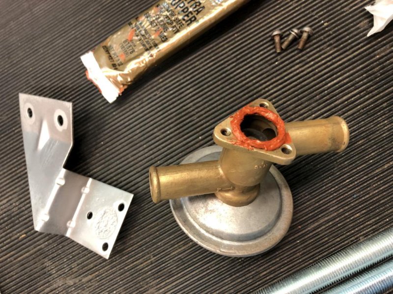
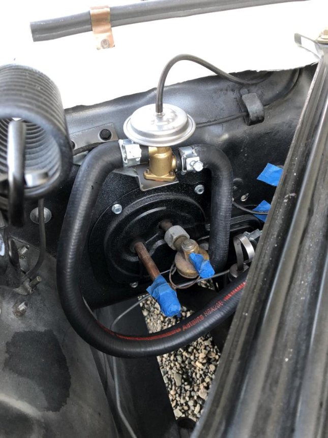
Then, since I was thinking about the cooling system, I figured it was time to install the heater hoses. To start with, I got a good original heater control valve (with A/C) and put in a new o-ring with some high temp sealant.
Then I had to figure out how the hoses route. Surprisingly, I couldn’t really find any good pictures on the internet of how they’re supposed to go. The best I could find were a couple of original illustrations to go by, which was helpful, but real life doesn’t always work out as cleanly as an illustration. Anyway, this is where I ended up for the routing. Don’t forget that the short, left side heater core hose is sold separately. Of course I used the “concours” hose clamps. Note that 2 more individual clamps are needed for the water pump bypass hose.
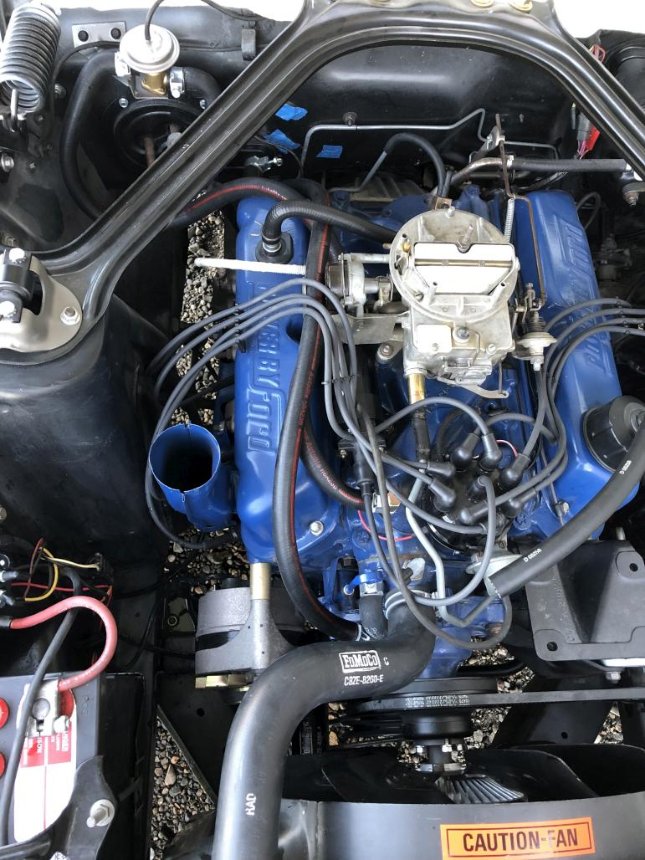
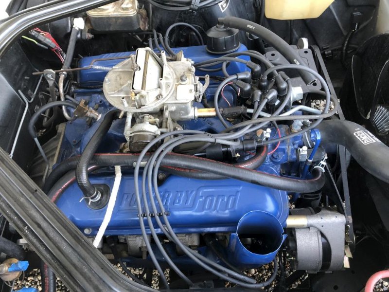
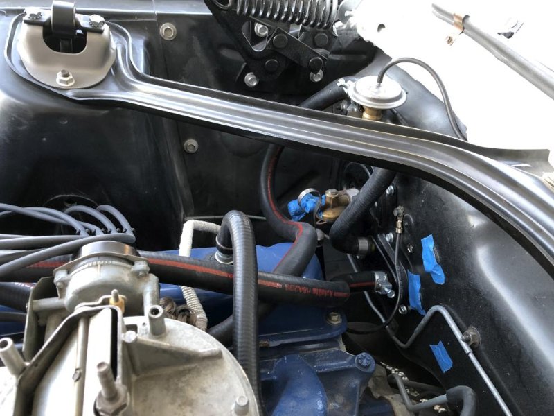
Hopefully I did that right and people in the future will find that helpful. The hoses needed a fair bit of trimming, even a little on the elbow sides. I found it worked best to have the elbows on the firewall side.
While I was at it, I went ahead and replaced the PCV hose.
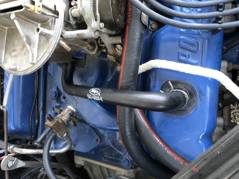
I still had my original on, because I thought it was cool at the time. But the original hose looked like this…
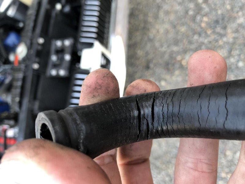
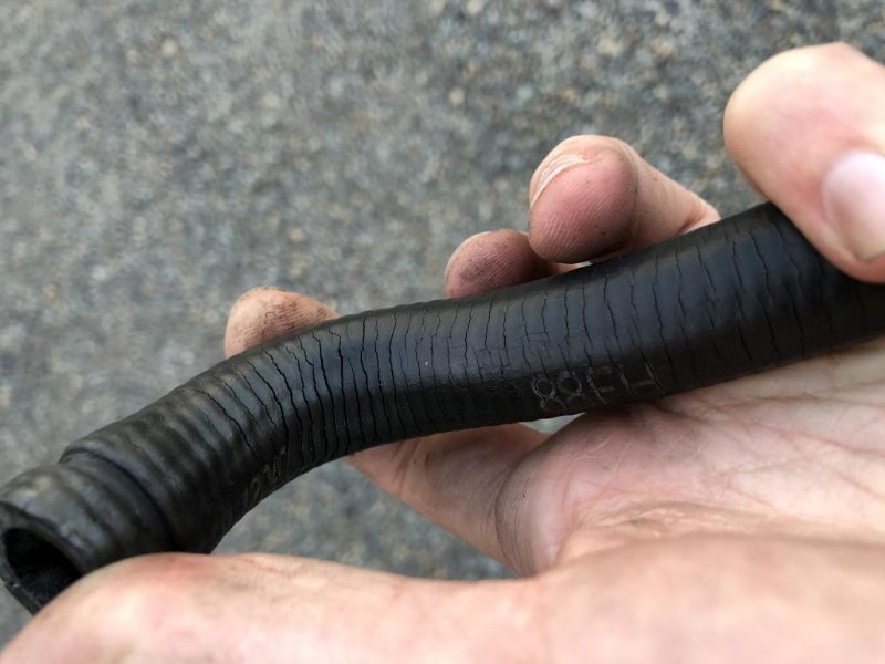
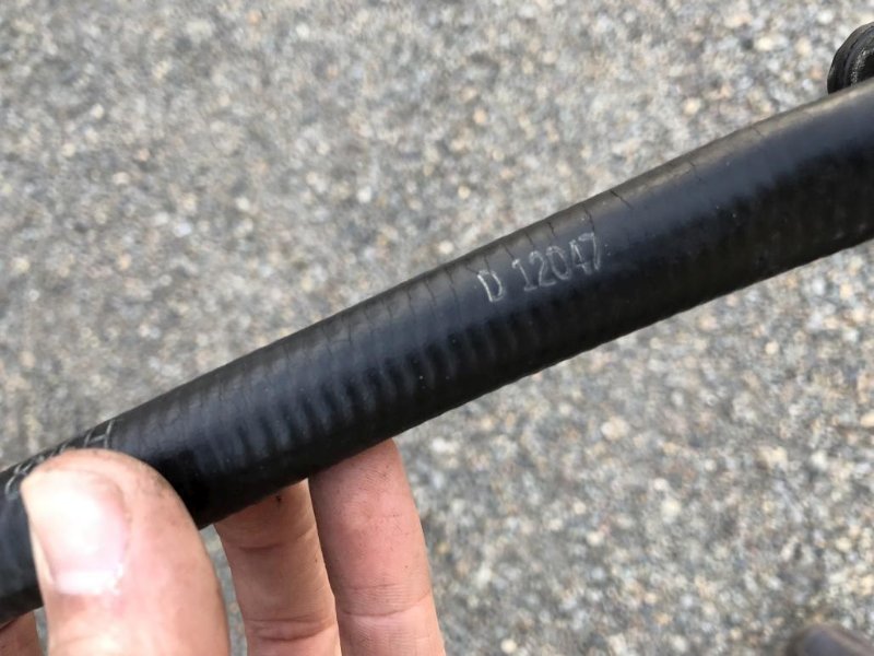
Just for nerdy posterity, here are the date codes and other numbers on the hose. 88FH and D 12047. Whatever that means.
A note about the spring wire hose clamps that hold this hose on - having the correct tool for these makes a big difference. Before I knew there was a special tool, I would struggle with regular pliers and they’d always slip. If you search for “hose clamp pliers” you’ll see a bunch of different versions, but what works best is one with rotating heads with the right size slots for the clamp. The one we have here at the shop is a K-D Mfg. Co. No. 429. There are new ones out there that look similar but pay attention to the configuration of the little round heads, many of the new ones are designed for different types of clamps. Here’s one that looks like it would work.
Anyway that’s all for now!
Andrew, on the regulator testing; these are shockingly invaluable relics if you are running any stock starting, charging, or ignition pieces on your car. Some guys laugh at me for having one on my work bench, but I use it quite a bit. I paid 20.00 for mine and it’s easily saved me 10x that in time and effort.
https://ebay.us/mlYyWn
The number 12047 could be a date code for Dec. 4th, '67. I searched your thread for your Marti and saw the actual build date in June '68 and know the 12047 is way before the build date, but that is possible. I have my original hose with the numbers 06108 (June 10th, '68) on it but my car has a closer build date of July '68.
Random update time! I’ve been driving the Cougar a little to shake it out (and use up gas so I could change the faulty sending unit). Here’s a random shot from a couple weekends ago.
Having determined that the instrument cluster was ok and there were no wiring issues back there, I could put the face pad back on. Also got the under dash lights installed and working.
Next… One experience driving at night with regular sealed beam headlights lights (misaligned) was enough to convince me to to the halogen headlight upgrade kit. I also opted for the regular clear bulbs instead of the blue-tinted ones that come with the kit. Out with the old…
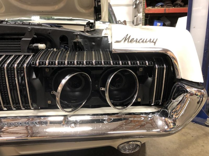
By the way, with the electric headlight motors, what I had to do was unplug the bulbs first, then turn on the headlight switch to open the headlight covers, then disconnect the battery. The springs that hold on the trim rings are a pain in the @$$ as most of you probably know. Who knew that changing headlights would be so cumbersome? For the record, this is the proper orientation of the springs:
This is another instance in which I think it’s worthwhile to have a special tool. If you google “headlight spring tool” you’ll see some options. Don ended up buying a used Snap-On version (HE52A or HE52B) for the shop, and I got to try it out. Made the job much easier. There are also versions with a T-handle and a hooked end which look like they’d work well too. Some drum brake tool kits come with such a thing.
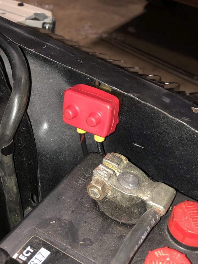
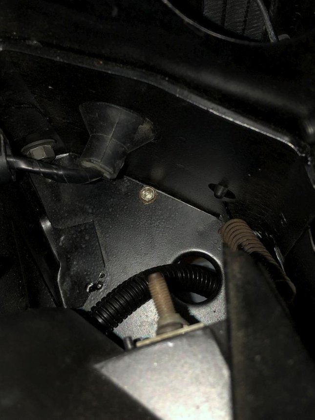
Anyway, I like the kit overall, kudos to Rocketman for making it user-friendly and almost totally plug-and-play. All you have to do is rearrange some plugs, make one cut and a couple crimps on the new power wire, and figure out where to route wires and hide the circuit breaker and relay box. I connected the power wire to the + side of the starter solenoid, since it already had a ring connector the right size. Then I ran the wire behind the battery and hid the circuit breaker under the lip of the core support, using an existing hole to mount it:
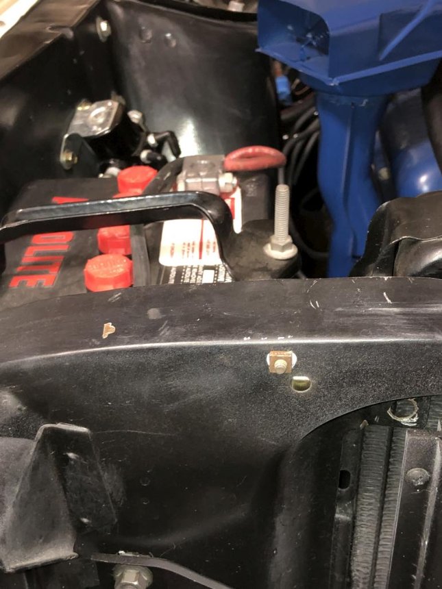
From the front, all you see is this little square nut, which I thought looked vaguely original. (Man my black under hood paint looks like poo now. Needs some detailing.)
The other end of the wire, I ran down beside the radiator and through the hole where the wiring harness passes through. The relay box, I ended up attaching to the underside of the RH headlight bucket using an existing hole in the corner.
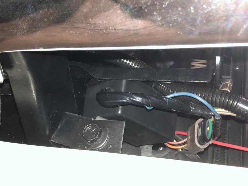
From the top, all you see is this little bolt in the back corner of the headlight bucket.
Long story short… BAM!
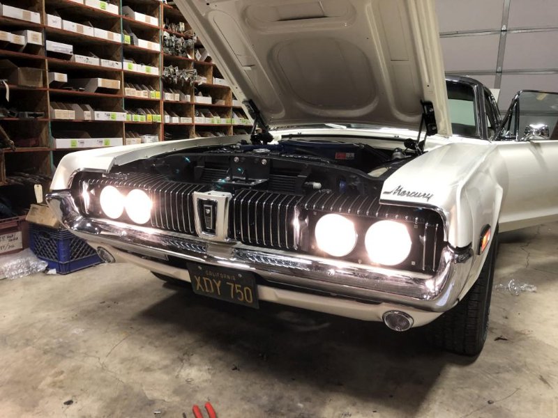
Much better light output. I still need to aim them, and for that I’ll use these guidelines from Daniel Stern Lighting. I’ve used these specs on my other cars (also equipped with E-code headlights) with great success. It should be noted that these new Octane headlight lenses that come with the kit are indeed E-codes, meaning they have the (superior) European beam pattern. So that will make these easier to aim. Anyway, more coming in next post, I’ve reached the 10 attachment limit…
In other news, I’ve still been trying to get the tuning dialed in. Finally found out that I had some pretty significant vacuum leaks at the intake manifold. So as much as I enjoy going backwards and redoing things, I got to pull the intake back off to re-gasket it.
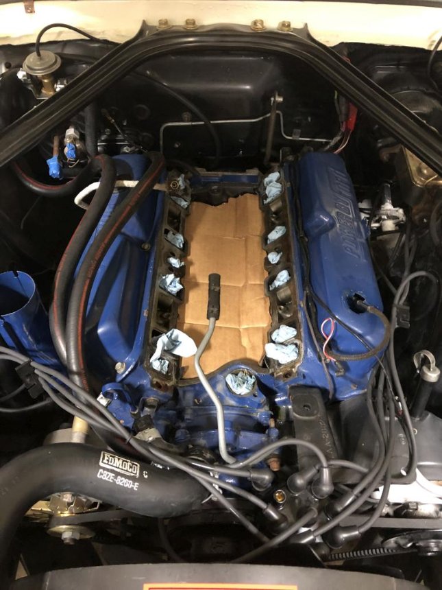
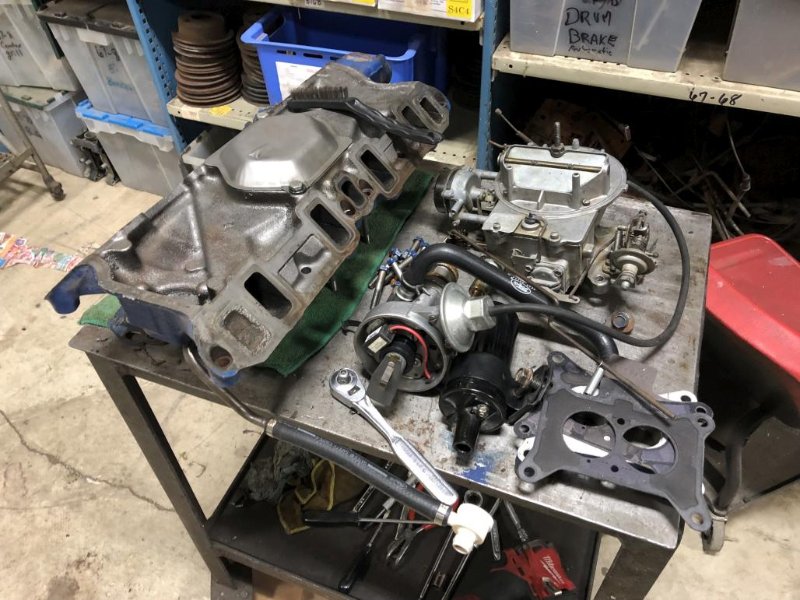
I couldn’t remember whether I had used sealant on the gaskets the first time - turns out I had only put sealant around the water ports, and the cork end pieces. The air ports were just dry. After some googling, I found out that many people recommend a thin layer of sealant on both sides, around every port. So, after getting all the surfaces cleaned up, I got new gaskets and did just that. As of writing this, the intake is back on and torqued, now I just need to button everything else back up. I’m looking forward to seeing how much better she runs now, fingers crossed that I won’t have any more vacuum leaks.
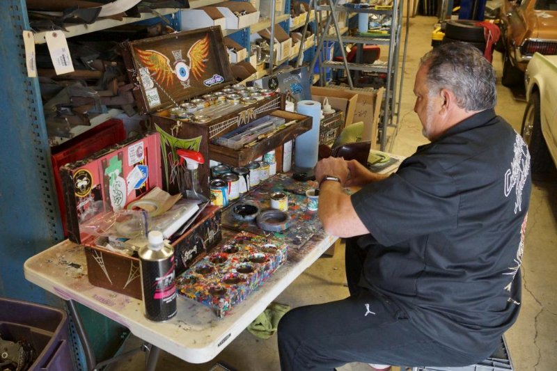
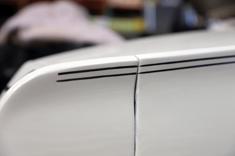
Next, in more fun news, pinstripes happened! This was just yesterday. Don was having pinstripes done on another Cougar here, so it made sense to egt them done on mine at the same time. This is Spiderman, a well-known pinstriper here in the PNW.
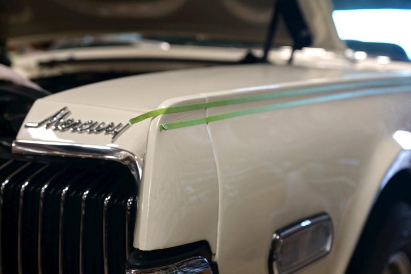
First he put down some tape guide lines. The top one is to guide him on the first stripe, and the bottom one is kind of like a track for his support finger to ride on.
So it begins:
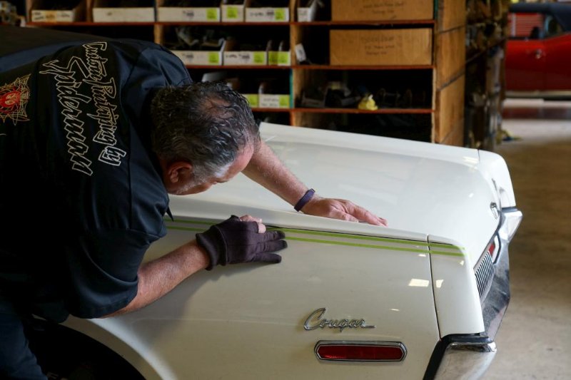
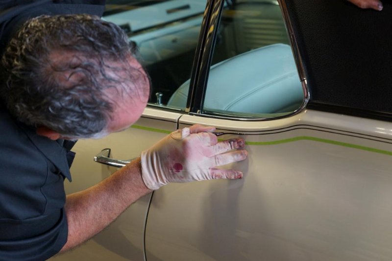
He didn’t like how the first stripe way laying out, so he wiped it right off with a wax & grease remover, changed gloves, fiddled with his brush and started over. Especially impressive was to see how well he dealt with this curve in the body line:
The end result is a really clean & classy pair of pinstripes that look very close to factory, but a little better IMO. They’re nearly perfect but I like that you can still tell they were hand painted. After all the research I’ve done on original pinstripes, I decided not to have him put gaps at the panel seams, like a '68 would have had from the factory. After looking at the end result, and how the stripes flow from one panel to another (without wrapping around), I thought that it looks great and didn’t want to mess with it. After all, I’m not really going for total concours.
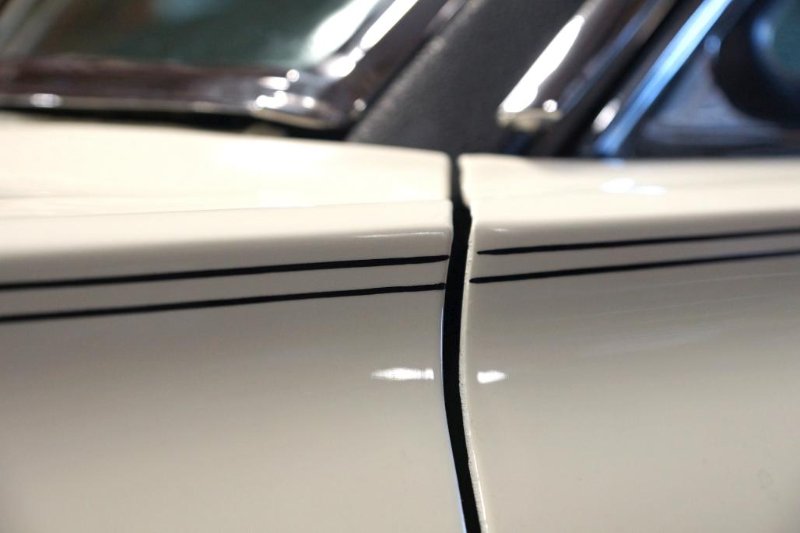
I’m happy with how they turned out! Really adds a touch of class to the car. Anyway, that’s all for now!
Wow, awesome! I guess I missed the post where you had it back out on the road. That’s great!
Maybe now I’ll see you at Cars & Coffee in Wilsonville some time?
Car looks great. Excellent update posts, as always. Can’t wait to see what’s next ![]()
What is wrong with the sending unit?
Thanks Mike! Not a bad idea, I’ll have to see if I can make it one of these times.
I’m kinda mystified… repro stainless steel standard sending unit (this one) was reading about 1/4 tank with the tank full of gas (right after filling up at the station, 10+ gallons and it splashed out of the filler neck a little). Tested the gauge to make sure it was ok by grounding the wire for the sender, which made the needle peg past full. Also did the test light on that wire and got the pulsing signal, so that all seems fine. Once the tank was close enough to empty, I drained it and removed the faulty sending unit. Took it to the bench and tested the resistance from empty to full and it all appeared to be within spec. Tested the float and it was fine. Even plugged it back in to the car using a jumper wire for ground and played with the arm, and got it to read full on the gauge. So I have no idea what the problem was. For now I’ve installed one of the cheaper generic units (this one) which also seemed to test ok, though it’s not as well built as the stainless one. At this point I don’t know for sure what the status is, since I only had about 4 gal from the fuel can to pour in. It’s reading around 1/8 tank, somewhere in there. Guess the only way to know for sure is to go fill 'er up again.
All the hard work (and re-work) is paying off: Snowball looks great!
(And I’m happy to see you included pinstripes.)
Details, details… amazing how much there still is to do even when it seems mostly done. This past weekend I did a couple of cosmetic projects, the easiest of which was to restore the original jack.
Before:
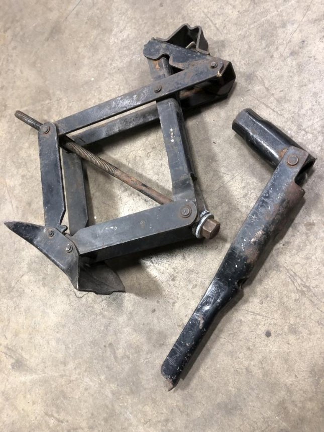
Bead blasted:
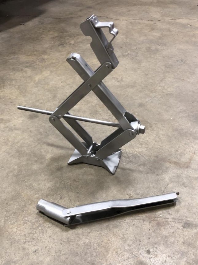
All finished, after painting with VHT Rollbar & Chassis paint (it’s been a good go-to satin black paint) and applying the little “See owner’s manual for jacking instructions” decal.
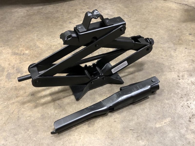
So now I can never use it again.
Next for a little nerdy touch… I splurged and got a NOS gas cap from someone on ebay.

The main reason for getting an original is that the repros don’t vent in both directions, which I learned from Kurt Lawrance at the 2018 WCCC open house (there’s a little segment on it in the video). Here’s the thing, though. I don’t think this NOS one vents in both directions either. I just drove to the gas station yesterday to fill up, with this cap installed, and as soon as I popped it off, there was a WHOOSH of pressure being relieved. Not sure in which direction. But there shouldn’t be a pressure buildup if this cap worked correctly, right? Ironically, I’ve never had that happen with the repro cap that I had on previously.
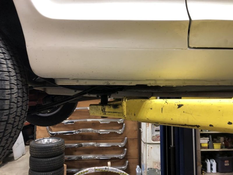
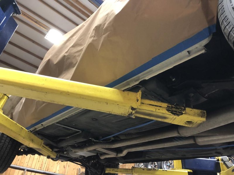
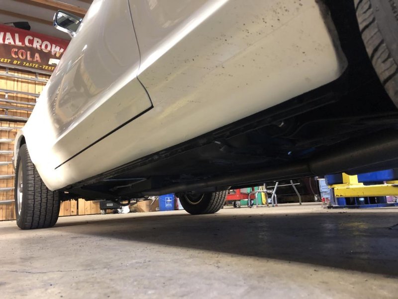
Anyway, on to the bigger project of the past weekend. I’ve been wanting to do this for a while. It’s another case of deja-vu, since I did this after the first time the car was painted. Point is, I wanted to black out the pinch welds, and while I was at it, fog over some of the white paint overspray that got on my previously nice looking undercarriage. Here are some before pics, pardon the dirt.
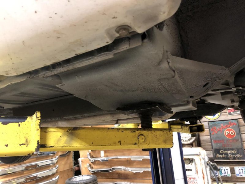
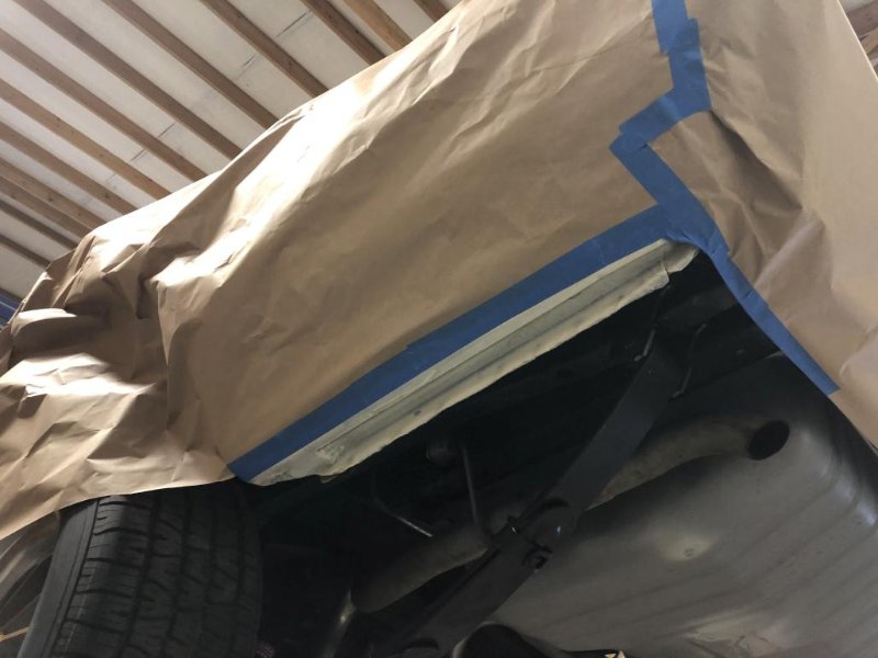
Let the masking marathon begin again…
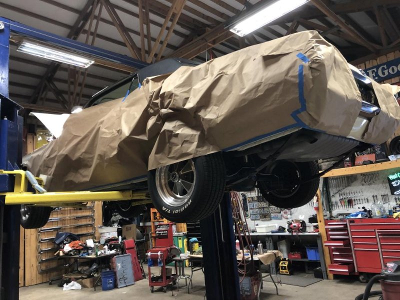
More to come in next post.
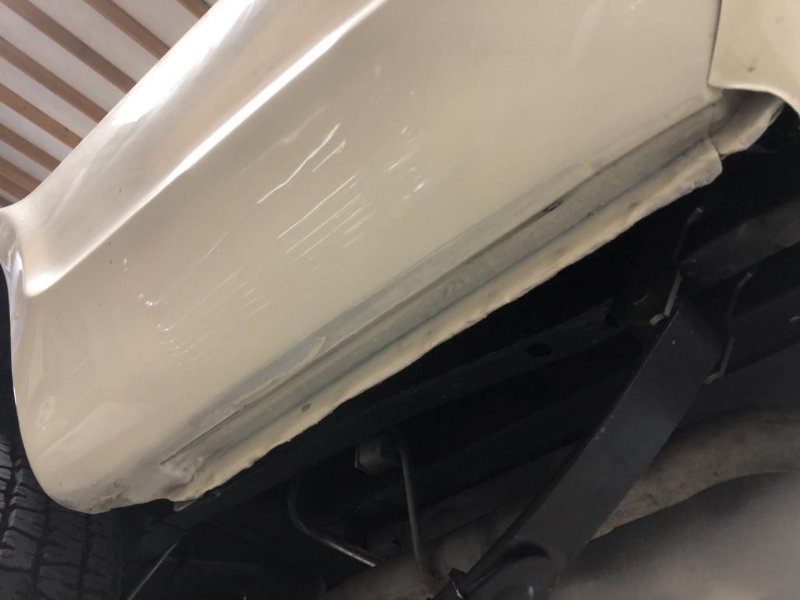
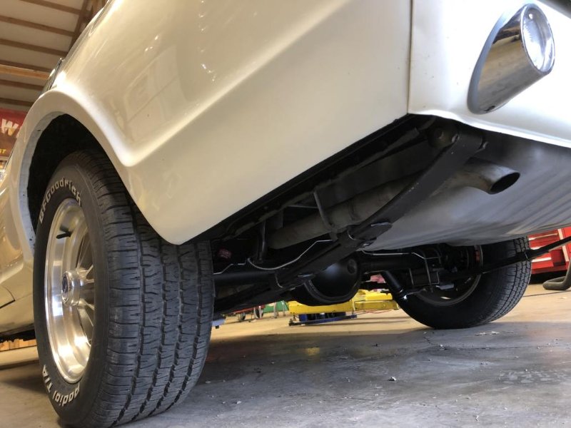
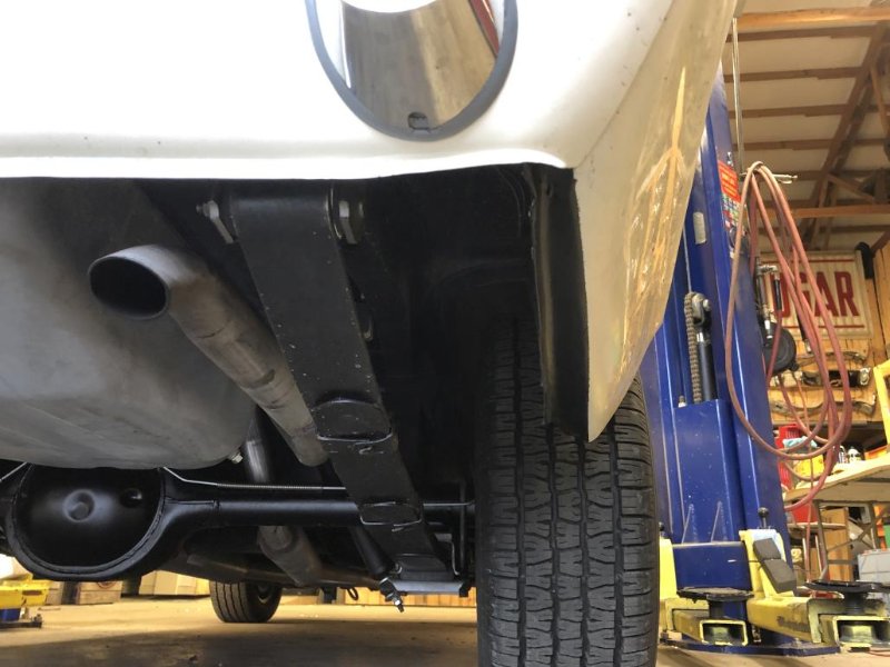
So this time around, I decided to go a little further outboard with the black paint than the factory did. I basically wanted to black out the whole horizontal bottom surface on the rockers, quarters, and fenders. Part of this choice was to hide thin paintwork, but I also thought it would provide the cleanest body line when looking at the car from the side. The fenders originally did not get any blackout paint on the bottom, but I went for it, in order to follow the same line that was established on the rocker panels. This worked out well on the quarters too, because it ends up creating perfect-looking corners where the valance meets the quarters.
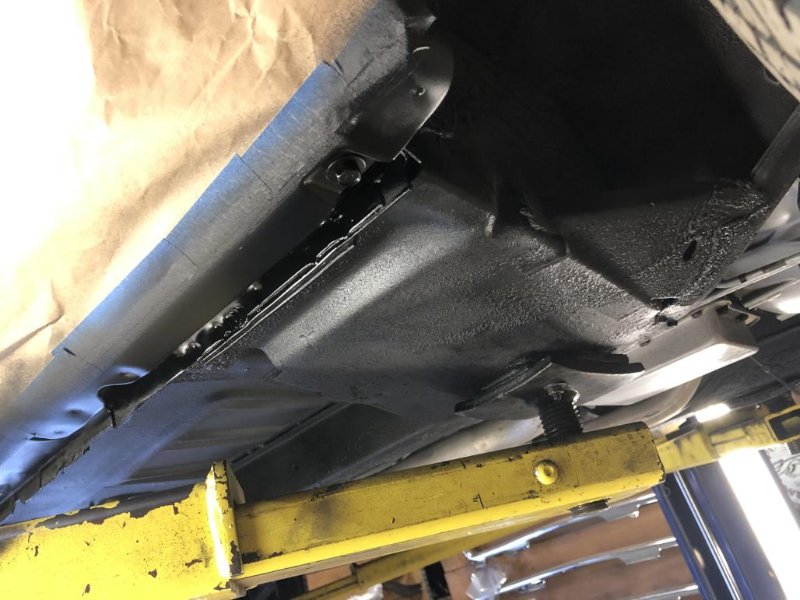
A couple “pre-spray” pics:
This one shows the section of the fenders that got painted, and the beginnings of improving the underside.
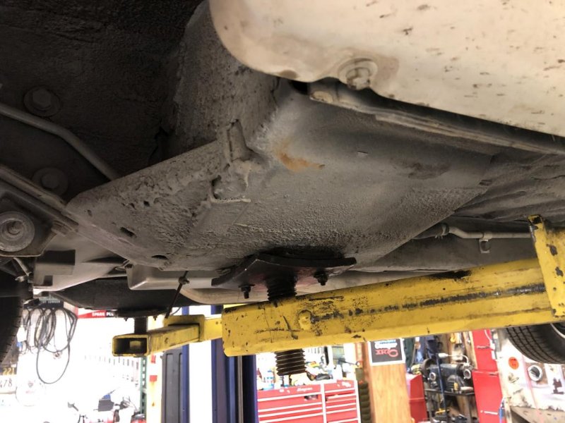
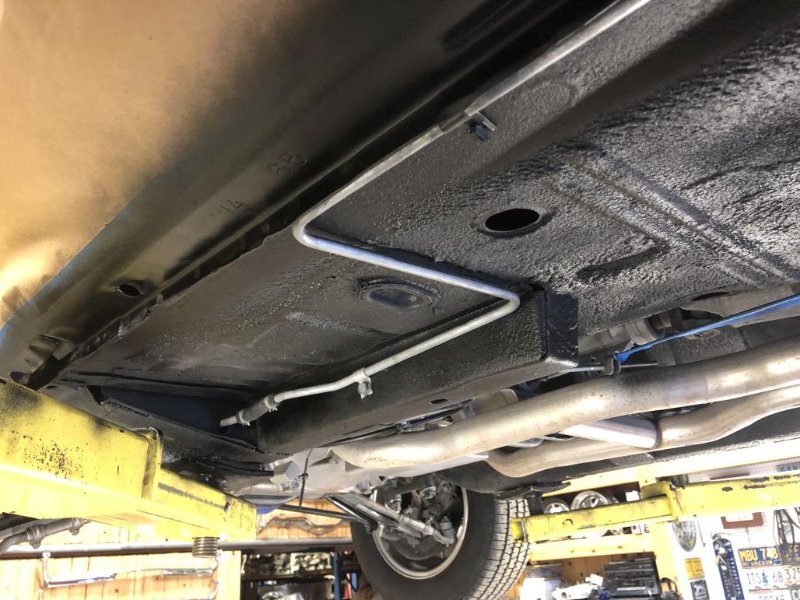
This is a much-improved floor area after fogging with black. I did partially mask the front part of the fuel line, but it ended up being easier to quickly wipe it off with wax & grease remover while the paint was still wet. I did put masking tape over the parking brake cables. You know you’re a nerd when…
Here are some initial “finished” shots on the ground. You won’t get the full effect until I can get some good full-body pictures outside, but I’m really glad I took the time to do this detail. It makes the bottom body line look clean and crisp.
That’s it for now!
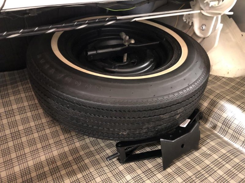
I would have thought the jack would sit on top of the spare. But I must confess I really don’t know.
Looks great Andrew! For some reason the pinch welds always grab my eye when they aren’t blacked out.
It doesn’t go on top, but I may not have done it exactly right in my picture. Never thought I’d be researching exactly how the jack goes in the trunk, but here we are. Here’s a look at the decal in the trunk. I think this might be why the top part of the jack swings up, I was wondering about that. Looks like it hooks to the J bolt, or the bracket in the floor. There are marks on the arms of the jack which I think show where you’re supposed to set it for stowage.
I’ll mess with it and report back.
Thanks! I agree, it makes a big difference. Many people just don’t think about this detail.
If they are working properly original gas caps only let air in the tank. They don’t let fumes out of the tank. So the classic mistake is to fill the tank up on a cold night and then put the car in a warm garage. The fuel will expand when it warms. If you inadvertently remove the gas cap it will give you a face full of fuel.
Not sure what Kurt is thinking. That’s how they are supposed to work.