Hi all,
I recently purchased my dream car, a '67 Cougar XR7. The car has a '73 302 in it and a 4-speed. Needs a ton of work starting with the fact that it runs but doesn’t start from the key. Previous owner I think was rewiring the dash. Anyway, when I purchased the car, he hooked up a couple wires from the battery to the starter motor relay and showed me that the engine is operable. I’m trying to get it to start from the key. I replaced the starter motor relay just about an hour ago and now when I try to attach the battery the car lurches forward (parking brake doesn’t work) without the keys even being in the ignition. I’m thinking that he (the previous owner) screwed something up around the ignition switch. Maybe it’s like permanently hot wired? Should I replace the ignition switch or look through the wiring of the dash first? Any suggestion where the fault might be?
Get a service manual. You can buy the reproduction manual pretty cheap from most vendors. It will have the wiring diagram for the ignition switch in the manual. Then start tracing wires and see if everything is wired correctly first. The manual will also help you out with the rest of the Cougar as you move foward with getting it road worthy. Congrats on your new Cougar purchase.
The starting system relies on 7 major components
- Battery
- Ignition switch
- Neutral Saftey Switch (automatic transmissions, note some manual transmissions used a saftey swith built into the shifter)
- Tilt Away steering Starter Neutral Switch (if equipped)
- Starter solenoid
- Starter Motor
- Tachometer (if equipped, affects only the ignition circuit once the engine starts)
Powering up the ignition switch:
Power from the battery is supplied Starter Solenoid’s Battery terminal. Attached to this terminal is circuit 37 (Black Yellow) that runs to the firewall’s flat 4 prong connector. Circuit 37 then coninues into the passenger compartment where a main splice in the harness feeds multiple sources which includes the following:
clock (circuit #22 Blue Black)
brake light switch (circuit #10 Green Red),
headlight switch (circuit #25 Black Orange) and
ignition switch (circuit #21 Yellow)
The ignition switch circuit attaches to the switch’s B post. When the ignition switch is turned to the Start position, The B and S posts connect providing power to circuit #32 Red Blue.
When the ignition switch is turned to the Start position, power from the ignition switch goes to a 4 wire square plug located under the dash near the steering column. If the car has an automatic transmission, the wires go to the neutral saftey switch located on the transmission case. Note the neutral saftey switch connects the circuit only when the transmission is in the Park or Neutral position.
Cars equipped with tilt away steering then route through to a starter safety switch located on the steering column near the vacuum motor so the car cannot be started in the tilt away position. See http://www.concoursmustang.com/speegle/67%20Mustang/Article-67Tilt.pdf
Power then goes back to the square firewall plug on to the starter solenoid’s S wire Circuit #32 (Red-Blue) wire. This in turn engages the starter solenoid’s internal coil and closes the solenoid’s plunger to provide 12 volts to the Starter (via the cable from the starter solenoid’s post opposite the battery connection to the starter) and the I wire circuit #262 (brown) wire. At this point the circuits are complete so that the starter motor should engage and crank the engine.
However for the engine to fire, the i wire Circuit 262 then goes back to the firewall where it connects to the ignition circuit’s #16 (red-green) which goes to the coil, providing power when starting. (Note: the power draw by the starter motor consumes 100+ amps and thus power provided to the I circuit will measure roughly 9 volts, not 12 volts. This is why the resistance wire is bypassed during starting and not to give a brief 12 volt jolt to the ignition systems when starting!!!)
Once the car fires and you return the ignition switch to the Run position, the S circuit disengages (the starter stops cranking) now the ignition switch disconnects the B and S circuit but powers the B and I circuit.
Note the connector at the firewall also connects circuit #16 (to the coil) and the ignition switch on circuit #16A (the pink resistance wire). When the car starts and you return the ignition switch to the “Run” position, power to the coil is now provided via the ignition switch on circuit #16A at a reduced voltage of 8 to 9 volts. If you have an XR7, the power from the resistance wire goes to the Tachometer then to the firewall. If you do not have power at the coil in run position with an XR7, place a bypass wire across the tachometer and retest for power at the coil. Note if the car is running, and you put a Voltmeter on the Starter solenoids I post, you will also read 8 to 9 volts because the wires are all connected at the firewall thus backfeeding power from the resistance wire.
I hope this clears things up.
Coach Jack
Usual suspect is the starter solenoid. New ones can be junk.
(Edit: spelling.)
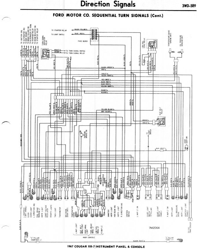
Yes, unfortunately the “concours correct” starter solenoids look wonderful but often stick giving the exact symptoms that you describe. Attached is the wiring diagram showing the colors of the wires and where they hook up to the starter relay (solenoid).