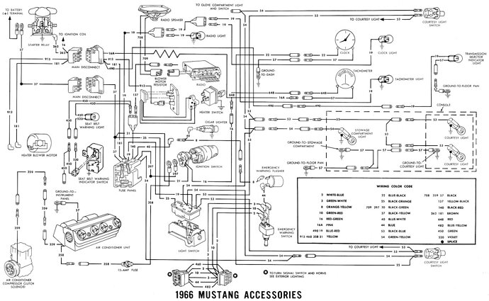
Pertronix install

I’m very gratified that we have found ( a little ) common ground re this discussion. Yes, I have never, and would never, use the stock Ford 6v coil in my P-1 conversions. I feel the MSD Blaster II epoxy filled coil is a better quality product than the Pertronix equivalent product. However that is just a subjective conclusion. They can be painted black with a yellow top if a stock-like appearance is desired.

A yellow paint that you might consider using is the CAT yellow found on all CAT equipment. IMHO it’s a closer match than the JD yellow.

I’d like to express my very lonely stand regarding the Pertronix ignitor products. For many years I’ve used them, but primarily have personally used the top of the line MSD ignition for about 15 years. I gravitated away from the Pertronix ignitors because they seem to have very little quality control, an area the MSD products excel at. I’ve have numerous 1st time customers car towed in with Pertronix I failures (I didn’t install them). And I’ve seen all kinds of failures, DOA out of the box, died when the motor gets hot , and also those which exhibit an intermittent miss. I know the majority of them work as advertised. But these well documented failures are why it’s common practice to keep a set of points in the car so you won’t get stranded. That is one reason I make it very easy to revert back to the original wiring. If someone comes to me these days and wants an electronic ignition, I won’t put in a Pertronix product, and will use MSD only if I can’t talk them out of it.

After drinking the MSD Kool-Aid fro 15+ years, I took a bet with a car pal, who said that my '66 GT350 would run the same and start the same, and idle the same, and have an identical dyne run with the stock ignition in place. I lost the bet. My car lost zero power, and idled the same with the stock ignition as it had with a MSD Digital 6+ ignition box and the top of the line MSD HVC-II coil.

Most people compare a Pertronix ignitor or an MSD ignition with their existing stock ignition which invariably has dirty or worn out points, or a failing condenser. Under those conditions the Pertronix is always going to give a better idle, etc. Apples to Oranges. These folks have a car that is running poorly, and rather than learn why, they assume that the problem must be outdated technology. Usually these people have no history using this old technology and don’t understand what maintenance is required.

Since that wager about 8 years ago, I threw out the Kool-Aid & replaced my MSD set up with a set of high quality points and condenser, and a used Ford yellow top coil (not a repro). Since then, I put nearly 25,000 miles on the GT350, and nearly 20,000 on a '65 K code, all with the stock ignition components. I adjust the point gap and dwell once every 7,500 miles. Not a lot of maintenance for me, but I understand that 10 minutes every year or so might be more than someone else would want to do. But when someone says that a lot of time is required to maintain a stock ignition, and to set points and dwell correctly, this is just not borne out by the facts. Also its just not the case that the idle is better with a Pertronix ignitor or a MSD box and distributor IF the points are not worn out or dirty. But, that doesn’t stop the companies that sell these products from using unfair comparisons in their advertising.

More voltage to the spark plug is something that the electronic manufacturers do have right. But this increased voltage is just not required to have an excellent running vintage car. It does sound impressive though, but adds nothing to the performance of a well tuned car.

I did have one customer who hounded me incessantly to install a P-1 ignitor, because, as he said, “the car won’t run right with points”. Finally I secretly installed a new set of echlin points and condenser from NAPA, and set the dwell and timing. He picked up the car, but before i let him pay me I told him to drive the car around for 30 minutes, them come back and tell me how it performed.

You can see where this is going. He came back and raved about the drive. The car ran better than ever before, it idled smoothly, it was the best money he ever spent, etc. etc etc.

I broke the news to him that he was driving around with a well adjusted points and condenser, and that I would put in a Pertronix ignitor for free if he ever felt the points weren’t providing the performance he wanted. Once he got used to the idea that he had been fooled, he began to warm up to the idea, and now I couldn’t get him to switch if I wanted to.

regards,

Z
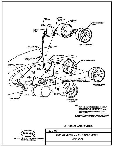
Zray: Your method will work if and only if there is not a tach in the circuit. The tach requires current flowing through the pink resistor wire, and if you bypass that resistor wire with essentially a zero resistance wire, then the tach will see no signal. There are other sources for RUN-only in the engine compartment: the one that comes to mind is the green/red wire at the voltage regulator.

As for current flowing through the pink resistor wire, I know for a fact that it is a nominal 1.3 to 1.7 ohms. However, when current flows through it, the nichrome wires heat up and resistance increases, essentially limiting the amount of current that can flow through it. It essentially acts as a current choke. This reduces the overall current from the ignition switch to the coil, but I will disagree to a certain extent about comments made about the ignition switch current capacity. There are several other RUN-only lines on every 67 on up Mustang and Cougar that also demand current at that ignition point. I suspect the ultimate capacity of the switch is limited by the wire size at that connector pin, which would typically be on the order of 10-15 amps DC, rather than the internal switch mechanism itself.

Not trying to beat a deceased house, but then how is it to be explained that my original Faria tach in my GT350 and the Ford tach in my ''65 K code all worked like a charm for years with the pink wired jumped, and continued to work OK when I reverted back to a point ignition ? In those cars the current ( and wiring ) went like this
Ignition switch to tach, then
to pink wire which has a 12 gauge wire attached to it at the first inch and also at the last inch, jumping it since the current follows the past of least resistance. Then on to where
Then it went into the firewall plug .
Then the circuit continued directly to the coil positive terminal where it met up with the Pertronix red wire.

The tach worked because it still was part of the circuit even though the pink wire was bypassed. The current had to go thru the tach in order to get to my bypass wire .

When I wired the car for the MSD digital 6+ box I removed the jumper wire which put the resistor wire back in full operation. It went then not the coil but to the MSD box trigger wire ( I can’t recall the color MSD uses for that), the trigger wire really didn’t need a full 12v , just a signal, since the MSD box main power wires went directly to the battery pos. and neg. terminals.

I have a feeling I’m not being clear because English has always tripped me up, even though it’s the only language I know.

Regards

Z

PS. I feel like I owe all the readers of these posts several beers for the agony they have endured in reading them.

PPS. I don’t pretend to know the tachs signal requirement, I just simply believe what I’m seeing when the tach needle moves clockwise every time my right foot moves downward.

PPPS. Disclosure: on some MSD installations I’ve had to use the MSD accessory box #8920 tach adaptor to get the factory tach to display accurately. But never had to do anything special like that when wiring up a Pertronix product

Z

Ahhh…I see what you did. I was reading the figure where the jumper coil lead is tapped before the tach and goes directly to the coil.

yeah, my jumper wire was just on each end of the resistance pink wire. In the cars on which I’ve done this, the resistance wire is after the tach.

like this:


Don’t know if some later years had the resistance wire between the ignition switch and the tach, but I’ve never seen it place there.


regards,

Z

A good set of points and a quality capacitor (aka condensor) work fine so long as they are properly gapped to get the dwell right. The hardest part is getting good parts to begin with.

In particular most of the problems I see with points and condenser set ups are related to poor quality parts. Condensors used to be filled with polychlorinated byhenyls (PCBs). They lasted almost forever and the PCBs were about as close to ideal for a dielectric and and coolant for transformers and electrolytic capacitors. They were also among the most noxious pollutants ever to exist. when they took PCB’s out of production the substitutes were not very good particularly in high temperature environments. We still lack a really good replacement. When the condensor begins to fail the points start to arc a little and you can start to see pitting or burning. That can be fixed temporarily by filing them flat.

One other issue that I see on our old cars is that the distributors are developing a bit of wobble. When the shaft wobbles you will see it when you check the timing as irregular shifting on the timing back and forth by a few degrees. If you are looking at a dwell meter you will see the same thing. Of course the correct fix is to rebush the distributor, but it does seem that the Pertronix isn’t effected by these small movements.

I completely agree that when you get a huge improvement in around town drive-ability with any after market ignition system, your base line was probably worn out or out of adjustment to begin with. I do like running the Pertronix in my cars because it looks stock, I never have to mess with it, I absolutely hate changing plugs on the 390 427 and 428 when installed in a Cougar, and with all the carb issues caused by alcohol in gas, it is easy to foul a set of plugs… and the slightly hotter spark seems to reduce fouling. At least it makes me feel like it does…

I don’t know if we really want to have a discussion on switch ratings but the type of load you are switching is a big factor. Regular old incandescent lamps are the hardest load to switch. When cold they have very low resistance so they pull a lot of current. The filament acts like, and is, a positive temperature coefficient thermistor. What that means is that as soon as the filament starts to heat up the resistance rises very quickly greatly reducing the amount of current passing through the circuit. A switch that may be rated for 15 amps to a purely restive load will be down rated to just 3 amps for a lamp circuit. The second hardest load to drive is an inductive load. And that is exactly what the ignition circuit is. Another name for a coil is inductor. The same 15 amp rated switch gets down rated to 10 amps for inductive loads.

When you spec a switch for particular application, you really need to know all of the parameters of the circuit. Event the speed at which the switch opens and closes is important. The good news is that at least we are dealing with low voltage. High voltage DC is the hardest thing to switch. If you were trying to decide if a switch will work for your application, if it is rated for 250 volts DC, it will handle 20 to 30 times that much current at 12 volts. High voltage AC is easier to switch by a factor of about 4.

This is why I like relays so much. The typically have a little device called a metal oxide varistor MOV (aka catch diode)that shunts away the inertial charge that wants to jump the gap in the contacts. They also switch must faster than any conventional switch.

Since you mentioned relays, I’ll give a plug for my favorite vendor for lighting upgrades. I’ve purchased a few sets of relays, H-4 bulbs, and Cibie lends form Daniel Stern. He’s a great guy to talk to and you’ll have to talk to him as he won’t sell you anything without a consultation.

http://www.danielsternlighting.com

The combination of the curved Cibie lenses, which look much better than the flat lenses often found, and a quality relay, and the H-4 bulbs cannot be believed if you’re used to stock lighting. A very nice safety upgrade. I drive vintage cars a lot cross country, so lighting is very important.

Z

I have had a 67 XR7 with the petronix installed as the instructions called for which here is called “a bypass installation” and the car has worked past my expectations for over 13 years and for a good part of that time I had a working tach too. As of today and over the years the tach has been working but not in a useful way as the needle takes many different positions and more often than not they are not accurate. I have been using a factory coil. Thanks for having this discussion so the rest of us can learn how to be able to enjoy our car so much more.

No, it’s not HID lighting. As I understand it, HID lighting might require a higher output alternator. But I (admittedly) really don’t know much about HID lighting. But don’t they require a special ballest etc.??? pretty sure they do. The H-4 bulb conversion really only requires a relay for safely sake. But a stock-like 61 amp alternator has no trouble keeping up with the demand. I also had an air conditioner added to the '65 K code, and still was not up against the stock charging systems limits, not even close. The H-4 bulbs and Cibie lenses were such a great combination, and provided so much usable light I became very enamored with them. And they didn’t blind oncoming traffic AT ALL, like so many of these aftermarket lighting systems do.

such a safety issue that aggravates me to no avail. I better not get started on clueless drivers……

Z

its possible a 12v coil might be called for in your case. I don’t know enough about how your car is wired to give any useful commentary. Perhaps others more familiar with your car could respond……

Z

Since it worked for a long time after installing the Pertronix, your wiring is probably not the issue, unless you have changed wiring in some other way. It does sound like a failure I have seen that was fixed by taking the tach apart and retouching all of the solder joints.

Bill to be sure what I have would be considered the bypass installation as I did the install according to Petronix instructions, a red wire tap before the pink resistor wire that goes straight to the coil The only side effect I have noticed is as Petronix says is that the coil gets very hot to the touch when the key is left in the on position and the car not running like when you turn the key on to power something your working on that doesn’t need the engine running (taillights).

it may be just me, but I wouldn’t wire 12v directly to a stock coil. If you change the coil to a 12v coil, thats different.

Z

Preaction, the new red wire should not go to the coil. It should only be connected to the Pertronix red wire. The only wire connected to the coil positive post should be the stock coil feed. The only wire connected to the coil negative should be the black wire going to the Pertronix in the distributor.

Zray is completely correct. You don’t want to run 12 volts to a stock coil. It will overheat.

IF the coil is getting hot then the Pertronix device is also under load. This is what damages or destroys the PI.