With all due respect, your replacement of the resistor wire, and my bypassing it with a jumper wire attached at each end of it, both techniques result in the same exact amount of current flowing thru the switch. There is zero current flowing thru the resistance wire when a normal wire is jumping it. Current will ALWAYS flow on the wire of least resistance. So there is absolutely no difference as far as current flow and the resulting heat is concerned . The amount of current does not increase as you state, because the demand of the ignition coil determines current flow, and the flow is identical with the Pertronix as it is with the points ignition . The type of coil alone determines the current requirement and the current flow, not the placement of a substitute wire or the placement of a jumper wire, either of which are identical in regards to current flow. As far as the tach goes , tach operation is unchanged as well. I’ve wired numerous Pertronix I’s for my Shelby and K code customers as well as for my own Shelby’s and K codes, in this fashion. Both of which use the same type of tach and attendant wiring as do the cougars in regards to those having a factory tach. Ignition switches in all cases continue to perform as normal with no rise in temperature internally or at the connections.
I’m not trying to convince you of anything . I’m sure we will agree to disagree. Just pointing out my experiences in wiring the P-1 in this manner when, on occasion, a full 12v is needed.
Regards
Z Ray
PS
this is EXACTLY the same as running a jumper wire along the ends of the pink resistance wire. (the pink wire having its end in the connection to the red w / green stripe wire (#16) at the ignition switch.) The jumper wire is bypassing the pink wire just the same if it was wired around as you are suggesting
PPS your new wire is taking the resistance wire out of the ignition switch / coil / circuit just the same as my bypass does. So if my solution is making the current increase to unsafe levels (and I’m not believing it does), then your new wire is doing the same exact thing, since it routes the ignition current onto a new wire with much less resistance, but is going thru the same ignition switch as always.
I will answer this in longer form, but what I described doing does not route the ignition current at all. It is a new circuit that only feeds the Pertronix Ignitor red wire. The coil is still fed by the same circuit including the tach and resistance wire. I think the Pertronix input impedance is in the 1K ohm range so current draw (150 milliamps?) is negligible. The original problem never was about the current draw of the Ignitor, it is about the voltage at the Ignitor.
Understood. As mentioned, I’ll agree to disagree with you on the effects my jumper wire has on the ignition current routed thru the ignition switch. My multimeter reading show no differences in current being routed thru the switch before or after the modification. Voltage at coil raised to battery voltage when jumper in place . Tested at idle to 5,000 rpm .
The Pertronix red wire in your wiring is hot from the ignition switch, but that same red wire also goes to the coil + terminal. As you say, the coil ( + terminal ) is also part of the tach and resistance wire. But no current to speak of is passing them the resistance wire with your wiring. It’s all going thru the new wire form the ignition switch to the red ignitor wire, which is also attached to the coil + terminal. So your wiring is not a new circuit at all. It’s tied into the original circuit by the connection at the coil + terminal. This is no different than my technique of just jumping over the resistance wire with a jumper wire , but leaving it in place. Whether the current is going from the ignition switch via a new wire terminating at the red ignitor / coil + terminal, OR goes by the way of a jumper wire that also ends up at the coil + terminal is of no consequence. The current thru the ignition switch is identical in both scenarios, and the Flow of current to the coil + terminal is also identical. The only difference between your method and mine, is my technique is easier to wire.
No you are misunderstanding the new circuit. It is not connected to the coil + terminal, only to the red wire on the Pertronix. It is there solely to provide 12 volts (or better) to the Pertronix Ignitor. The coil power supply is unchanged. You are eliminating a resistance when you bypass the resistor wire in the coil feed circuit. I understand how confusing electronics can be. The relationship between current, voltage, and resistance is defined by Ohms law. Current is equal to voltage divided by resistance. If you change resistance, you will also change the amount of current flowing through the circuit. How this effects the switch in the circuit depends in large part on the condition of the switch. The amount of current flowing through it is entirely a function of ohms law.
With all due respect for your efforts to educate me, In every wiring diagram that Pertonix supplies, the red wire is connected to the coil + terminal as well as to the ignition switch. That’s where it’s getting it’s 12v power.
Thanks for trying to help with my confusion, much appreciated, but not needed in this instance.
As mentioned , electronics is very confusing . But after over 100 successful Pertronix installations, I think I’ve got it down .
Regards,
Z
PS from pertronix instructions:
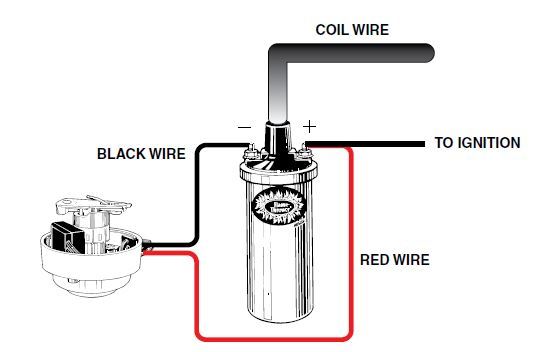
Attach the black Ignitor wire to the negative coil terminal. (See Figure A)
Attach the red Ignitor wire to the positive coil terminal. (See Figure A)
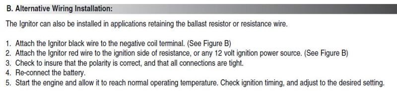
Zray I am sincerely trying to help you. People have done this installation wrong hundreds even thousands of times. The instructions Pertronix supplies are not very good. Even Pertronix admits that. Lots of folks make the same mistake. More importantly, I am trying to keep people from getting bad information that could result in damage to their car. You missed this part of the instructions immediately above the diagram:
Many vehicles came equipped with ballast resistor or resistance wire. To achieve optimum performance from the Ignitor ignition
system, we recommend the removal of these components.
• To remove a ballast resistor, (normally white ceramic blocks 3 to 4 inches long), disconnect all wires on both ends of the ballast
resistor. Remove the resistor from the vehicle and splice the disconnected wires together at a single point.
• To remove a resistance wire, trace the coil power wire, which was previously connected to the positive coil terminal, back to the fuse
block. Bypass this wire with a 12-gauge copper stranded wire.
AFTER you remove the resistor then you can wire it like this:
This is what you have been doing when you add the jumper to bypass the resistance wire. It will work, in that the Pertronix is getting 12+ volts, but it also feeds 12 volts to a 6 volt rated coil and that makes the coil run hot and pulls more current through the switch than it was designed to handle.
Which is why they also show the alternative wiring method which happens to be applicable to Ford products that use a resistance wire.
This is just wrong: “In every wiring diagram that Pertonix supplies, the red wire is connected to the coil + terminal as well as to the ignition switch.” Look at the instructions and see the following diagram from the instructions you just posted.
More instructions from Pertronix:
I am sure that you think I am just some guy arguing with you on the internet, but as it turns out i have been teaching people about 12 volt electronics for more than 35 years.
Perhaps you are a Mobile Electronics Certification Program (MECP) certificate holder https://mecp.com/. I helped create the program, and contributed to writing the training materials and exams.
I also spent over 30 years in my career in 12 volt electronics selling about $30 million a year in wiring products as a Managing Director at Rockford Corp (Rockford Fosgate, Lightning Audio, MB Quart, Q-Logic, etc) I have done training for Alpine, Kenwood, JBL, Polk and several other companies. I have developed products that went into production vehicles for Ford, Chrysler, Mazda, Nissan, and Honda.
With regard to the Pertronix Ignitor product I interviewed the engineers at Pertronix for a magazine article and following that interview wrote articles about how they wanted the product to be installed. Much of the misunderstanding of the product comes from its history. Initially it was not targeted towards consumers. The idea that a consumer would spend $100 to replace a set of $2 points was considered insane. The market as originally envisioned by Pertronix was fleet vehicles, specifically trucks. Those trucks got a new set of points about once a month, and the savings in tune up cost, fuel savings and spark plug life was easy to quantify. The instructions that they still use date back to those trucks. In particular the idea of a resistor wire was not something they encountered in those vehicles. They were very happy to try to get the correct way to do this out there. Following publication they asked me to share the information with other Ford groups. I am not sharing my opinions, rather the best information that the manufacturer offers. I don’t work for them, and we don’t even accept advertising here, so there is no commercial connection involved.
My initial post of how to easily remove the resistance wire from the circuit by installing a jumper wire at both ends still stands.
It’s the easiest way to get 12v to the ignitor and doesn’t damage any other parts, not the ignition switch, not the factory tach, etc. yes there are other ways to achieve the same results, however the method I posted is the easiest.
Regards
Z
PS. I’m not just “some guy” on the internet who likes to argue either. I’ve been building Ford engines since I was 10 years old, 56 year ago. I know what works, and what will damage an electrical system. When I have a car that’s been damaged by my work, I’ll be sure to admit it.
You do get that Ohms law is not a suggestion. If you reduce resistance, current rises. There is no getting around that. The method you describe potentially increases the current flow above the rating of the parts. If you are okay with doing that then knock yourself out. This stuff is well understood from an electrical engineering standpoint. I am sure that you are terrific guy and probably an excellent engine builder. I think your cross-member is a very cool part. I think you can contribute a lot to the community here. I am not trying to insult you. It is important that people understand the implications of what they chose to do.
thanks for the efforts in trying to educate me. I’m sure we will have many areas of agreement, and a few that can never be resolved. This is one of those that will not be resolved. And in past posts I’ve said as much, that we are going to agree to disagree on this one.
From my point of view, and my practical understanding of electrical circuits, my method of bypassing the resistance wire has zero effect of amount of current passing thru the ignition switch compared to your method. On numerous occasions, I’ve measured current at the ignition switch and there is no change in current flow after the P-1 installation when compared to the current flow before the installation. Your method of running a power wire from the ignition switch to the pertronix is identical in effect as my method of bypassing the resistance wire and had the same effect on current flow thru the switch. You are never going to see it that way. I don’t have a problem with that. It won’t be the first time I’ve led a horse to water but couldn’t make it drink. I’m sure you are feeling the same way.
regards,
Z.
PS the good news is that my crossmembers have no electrical connections.
Those are a great choice, if you are bypassing the resistor wire one would want to use the 40501 black 40511 in chrome or the 40611 epoxy filled. I am not sure that our cars require the epoxy fill. They are all 3 ohm coils and still output 40K volts. If you are leaving the resistor wire in place the 1.5 ohm coils are a good choice the 40001 in chrome, the 40011 in black, or the 40111 in black epoxy filled. Steer away from the .6 ohm and .32 ohm coils unless you are using a relay to provide the power. The coils are a bit smaller n diameter than stock so you might want to pick up a new bracket but the stock one can be made to work with a little modification.
Zray, using the Pertronix Flamethrower three ohm coils listed above are perfect together and won’t produce any problems with the switch or the tach when the resistance wire is bypassed. I am guessing that this is what you have been installing all these years. Many of the folks on this board are interested in retaining a stock appearance so they stick with the stock yellow top coil.
A black Flamethrower with a little John Deere yellow paint on top looks pretty close to stock. There are also stickers available for the coil to complete the substitution.
I’m very gratified that we have found ( a little ) common ground re this discussion. Yes, I have never, and would never, use the stock Ford 6v coil in my P-1 conversions. I feel the MSD Blaster II epoxy filled coil is a better quality product than the Pertronix equivalent product. However that is just a subjective conclusion. They can be painted black with a yellow top if a stock-like appearance is desired.
A yellow paint that you might consider using is the CAT yellow found on all CAT equipment. IMHO it’s a closer match than the JD yellow.
I’d like to express my very lonely stand regarding the Pertronix ignitor products. For many years I’ve used them, but primarily have personally used the top of the line MSD ignition for about 15 years. I gravitated away from the Pertronix ignitors because they seem to have very little quality control, an area the MSD products excel at. I’ve have numerous 1st time customers car towed in with Pertronix I failures (I didn’t install them). And I’ve seen all kinds of failures, DOA out of the box, died when the motor gets hot , and also those which exhibit an intermittent miss. I know the majority of them work as advertised. But these well documented failures are why it’s common practice to keep a set of points in the car so you won’t get stranded. That is one reason I make it very easy to revert back to the original wiring. If someone comes to me these days and wants an electronic ignition, I won’t put in a Pertronix product, and will use MSD only if I can’t talk them out of it.
After drinking the MSD Kool-Aid fro 15+ years, I took a bet with a car pal, who said that my '66 GT350 would run the same and start the same, and idle the same, and have an identical dyne run with the stock ignition in place. I lost the bet. My car lost zero power, and idled the same with the stock ignition as it had with a MSD Digital 6+ ignition box and the top of the line MSD HVC-II coil.
Most people compare a Pertronix ignitor or an MSD ignition with their existing stock ignition which invariably has dirty or worn out points, or a failing condenser. Under those conditions the Pertronix is always going to give a better idle, etc. Apples to Oranges. These folks have a car that is running poorly, and rather than learn why, they assume that the problem must be outdated technology. Usually these people have no history using this old technology and don’t understand what maintenance is required.
Since that wager about 8 years ago, I threw out the Kool-Aid & replaced my MSD set up with a set of high quality points and condenser, and a used Ford yellow top coil (not a repro). Since then, I put nearly 25,000 miles on the GT350, and nearly 20,000 on a '65 K code, all with the stock ignition components. I adjust the point gap and dwell once every 7,500 miles. Not a lot of maintenance for me, but I understand that 10 minutes every year or so might be more than someone else would want to do. But when someone says that a lot of time is required to maintain a stock ignition, and to set points and dwell correctly, this is just not borne out by the facts. Also its just not the case that the idle is better with a Pertronix ignitor or a MSD box and distributor IF the points are not worn out or dirty. But, that doesn’t stop the companies that sell these products from using unfair comparisons in their advertising.
More voltage to the spark plug is something that the electronic manufacturers do have right. But this increased voltage is just not required to have an excellent running vintage car. It does sound impressive though, but adds nothing to the performance of a well tuned car.
I did have one customer who hounded me incessantly to install a P-1 ignitor, because, as he said, “the car won’t run right with points”. Finally I secretly installed a new set of echlin points and condenser from NAPA, and set the dwell and timing. He picked up the car, but before i let him pay me I told him to drive the car around for 30 minutes, them come back and tell me how it performed.
You can see where this is going. He came back and raved about the drive. The car ran better than ever before, it idled smoothly, it was the best money he ever spent, etc. etc etc.
I broke the news to him that he was driving around with a well adjusted points and condenser, and that I would put in a Pertronix ignitor for free if he ever felt the points weren’t providing the performance he wanted. Once he got used to the idea that he had been fooled, he began to warm up to the idea, and now I couldn’t get him to switch if I wanted to.
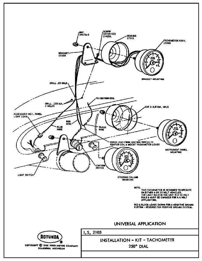
Zray: Your method will work if and only if there is not a tach in the circuit. The tach requires current flowing through the pink resistor wire, and if you bypass that resistor wire with essentially a zero resistance wire, then the tach will see no signal. There are other sources for RUN-only in the engine compartment: the one that comes to mind is the green/red wire at the voltage regulator.
As for current flowing through the pink resistor wire, I know for a fact that it is a nominal 1.3 to 1.7 ohms. However, when current flows through it, the nichrome wires heat up and resistance increases, essentially limiting the amount of current that can flow through it. It essentially acts as a current choke. This reduces the overall current from the ignition switch to the coil, but I will disagree to a certain extent about comments made about the ignition switch current capacity. There are several other RUN-only lines on every 67 on up Mustang and Cougar that also demand current at that ignition point. I suspect the ultimate capacity of the switch is limited by the wire size at that connector pin, which would typically be on the order of 10-15 amps DC, rather than the internal switch mechanism itself.
Not trying to beat a deceased house, but then how is it to be explained that my original Faria tach in my GT350 and the Ford tach in my ''65 K code all worked like a charm for years with the pink wired jumped, and continued to work OK when I reverted back to a point ignition ? In those cars the current ( and wiring ) went like this
Ignition switch to tach, then
to pink wire which has a 12 gauge wire attached to it at the first inch and also at the last inch, jumping it since the current follows the past of least resistance. Then on to where
Then it went into the firewall plug .
Then the circuit continued directly to the coil positive terminal where it met up with the Pertronix red wire.
The tach worked because it still was part of the circuit even though the pink wire was bypassed. The current had to go thru the tach in order to get to my bypass wire .
When I wired the car for the MSD digital 6+ box I removed the jumper wire which put the resistor wire back in full operation. It went then not the coil but to the MSD box trigger wire ( I can’t recall the color MSD uses for that), the trigger wire really didn’t need a full 12v , just a signal, since the MSD box main power wires went directly to the battery pos. and neg. terminals.
I have a feeling I’m not being clear because English has always tripped me up, even though it’s the only language I know.
Regards
Z
PS. I feel like I owe all the readers of these posts several beers for the agony they have endured in reading them.
PPS. I don’t pretend to know the tachs signal requirement, I just simply believe what I’m seeing when the tach needle moves clockwise every time my right foot moves downward.
PPPS. Disclosure: on some MSD installations I’ve had to use the MSD accessory box #8920 tach adaptor to get the factory tach to display accurately. But never had to do anything special like that when wiring up a Pertronix product
A good set of points and a quality capacitor (aka condensor) work fine so long as they are properly gapped to get the dwell right. The hardest part is getting good parts to begin with.
In particular most of the problems I see with points and condenser set ups are related to poor quality parts. Condensors used to be filled with polychlorinated byhenyls (PCBs). They lasted almost forever and the PCBs were about as close to ideal for a dielectric and and coolant for transformers and electrolytic capacitors. They were also among the most noxious pollutants ever to exist. when they took PCB’s out of production the substitutes were not very good particularly in high temperature environments. We still lack a really good replacement. When the condensor begins to fail the points start to arc a little and you can start to see pitting or burning. That can be fixed temporarily by filing them flat.
One other issue that I see on our old cars is that the distributors are developing a bit of wobble. When the shaft wobbles you will see it when you check the timing as irregular shifting on the timing back and forth by a few degrees. If you are looking at a dwell meter you will see the same thing. Of course the correct fix is to rebush the distributor, but it does seem that the Pertronix isn’t effected by these small movements.
I completely agree that when you get a huge improvement in around town drive-ability with any after market ignition system, your base line was probably worn out or out of adjustment to begin with. I do like running the Pertronix in my cars because it looks stock, I never have to mess with it, I absolutely hate changing plugs on the 390 427 and 428 when installed in a Cougar, and with all the carb issues caused by alcohol in gas, it is easy to foul a set of plugs… and the slightly hotter spark seems to reduce fouling. At least it makes me feel like it does…