I still use my old MATCO analog meter. It was actually made by Simpson for MATCO. It has a dwell meter and an amp meter shunt attachment that is great for measuring starter amps while cranking. I don’t know of a modern tool that would replace all that it does.
In my GT-E I use the Pertronix unit to replace the points in the stock Autolite C7OF 12127-F distributor. It controls an MSD 6AL which provides power to the ACCEL coil. None of the coil voltage goes through the Pertronix unit. All of the coil voltage comes from the MSD 6AL.
The system you describe is something I have zero experience with. I guess I would try wiring it the way Pertronix says to. If you have an XR-7 of course this means your tachometer won’t work.
Thx Royce. It’s obvious to me I don’t understand how ignition works.
My limited understanding was the battery/alternator supply voltage to the coil, which delivers voltage to the distributor which sends power to the plugs for spark via the rotor cap.
It sounds very different in your set up. I need to do some research on this MSD 6AL.
are you available for a phone call? Thx
Bill as usual is right on. Gosh Royce, My trailer park buddies must be smarter than yours. You started it big guy! No load 12 volts. Load will make it drop. Get your VOM out and check her out big guy! Guess I better log in every day to see comments. Time to change the tarp on my double wide!!! She be leaking!
The Mallory Unilite is far from fragile. I have run multiple Unilites on customer cars and not one has had a problem. Again running on the stock resister wire when loaded is around 7 volts. Coupled them to MSD 6ALs and such with no problems. I also have a Tach Adaptor on my car and the stock tach works just fine.
As far as plug cap, you can experiment opening the gap to .040 or .045. If your car has high compression and you use it on the track and/or spin it fast, stay at .035 even with a MSD box. The larger spark gap tends to get “extinguished” at high RPM in high compression engines.
Rob
Does any of this, including the quality of today’s fuel, change the stock spec from 1970 for timing at 10 degrees BTDC? Thx
This is a great chance to let Cougar members judge for themselves. I have posted these thoughts on many Ford sites. Todays gasoline is a very slow burning blend. The octane numbers (87,89, &91) do not represent a direct coalition to the octane numbers of the late 1960’s. Where premium was 99 and Chevron white pump custom supreme was rated at 101 octane. The slow burning gas blends of today react very closely to the high lead gas blends of the 1960’s in a high compression engine. I have ran a 12 to 1 extreme build solid roller cammed Weber inducted 289 on todays slow burn gases at 38 degrees of total advance. No pinging and great power. Todays slow burn gasses rated at 91 or 92 octane run great with old school high compression engines and anyone who tells you to reduce compression will help you build a dog motor. Anything lower than 10 to 1 will produce very poor power.
To address the initial timing question, I run as much as 12 to 16 degrees initial timing on all my Ford builds. Now this must be coupled to addressing the vacuum advance curve of a mild build. You need to slow down the vacuum advance and reduce its total. This can be done with springs and shims in a factory style vacuum advance or the use of a newer adjustable advance. To tune out low load pinging under partial throttle operation.
I submit this telling article from the early 2000’s. It was the results of multiple dyno pulls on todays gas and todays gas with octane booster. Also it addresses similar blends prevalent in the late 60’s. it supports that the earlier blends were so much more “explosive” that they had to actually reduce total timing in this Mopar 360 engine build. It display facts that I have experienced in many of my engine builds.
I am currently building a 53 CC Twisted Wedge combustion chamber, flat top 302, with a roller cam. It will run just fine on 91 octane gas with 12 to 16 degrees of total advance and 38 total. Fine tuning the vacuum advance total and start point. Also cam selection can greatly affect pinging as it will blead off static low RPM compression.
Please digest this article to alter your thoughts on todays gas and high compression engines. Yes, old school engines. It is hugely revealing! And don’t get me started on hardened valve seat! What a bunch of baloney!
Rob
https://www.hotrod.com/articles/fuel-octane-rating-comparison/
The voltage with the vehicle running is 6.5-8V. Not a question of if. It is. The Pertronix II, III will NOT run on the voltage through the resistor wire. The Pertronix I will. There is a trade-off. The erratic voltage destroys the ignition module. I always see dunderheads commenting about how the Pertronix units fail. Then find out they never pulled a 12V constant and run it directly. This is absolutely crucial with voltage sensing factory tachometers.
I had to do this on my 67 Shelby and it has to be before it passes through the tach.
-Keith
Thx Keith.
Pertronix does sell a “power relay” for this situation, supplying a constant 12 volts to the coil.
Have you used this part?
I cannot speak to a factory tach, but the Pertronix will run on the resister wire as stated. But it does need the Pertronix matching coil. I will post that part # tomorrow. Keith, please give some detail on the way you wired your car. I have a 68 Shelby GT-350 customer car in my garage as we speak. The owner wants me to upgrade to a Pertonix system for his car. Please provide the Pertronix parts you purchased and the hot wire source you used and where to hook it up. We all learn when you learn!! This is wonderful that you chimed in!!
Rob
Good discussion, but I’m still a bit unclear.
Is Keith saying the Pertronix I WILL run with the resistor wire and less than twelve volts to the coil, but that the module will fail?
My ignition wiring looks nothing like any electrical schematic I have seen, regarding wire color, so I would prefer adding Pertronix’s power relay than trying to figure out how to bypass the resistor wire.
This product review of power options for the Pertronix igitor was provided by Legendary Cougar Magazine August 2014 issue:
Thx Bob.
Six years later, any updates? When you say connect the orange wire to the electric choke OR PerTronix - do you mean the Pertronix coil or ignition module?
If you mean the ignition module, how is that done? I do have an electric choke and your three wire tach. Thx
Billy
The Ignitor.
The orange wire on both the P001 and P002 is switch B+ (battery voltage).
The coil voltage is controlled by the switch on the P001 (ballasted ~8V or B+) through the stock wiring.
The P002 has the 12V orange line but the stock coil wire is ballasted voltage only.
Thx Bob. That’s a bit above my skill set
The website says the P002 delivers a constant OEM 9 volts to the coil. I thought the goal was twelve volts to the coil?
When I get the Pertronix coil and distributor for my car, which part would you recommend? Thx
The P001 will give 12V (b+) to the coil. Just set the switch to 12V.
You have a three wire tach so that will not be effected.
The orange accessory wire can be used to power the Pertronix Ignitor.
All version of the Pertronix are 12 volt devices. When people say that it will work at low voltage, what they mean is it won’t fail right away. A few years ago I interviewed an engineer at Pertronix. They told me then they would appreciate any help they could get to clarify that you need to supply the Pertronix with 12 volts.
Eric Overton wrote a very good explanation
A long time a ago a very good electrical engineer and also Cougar guy wrote this:
From: Eric Overton
Date: Mon May 31, 2004 3:50 pm
Subject: RE: [COUGARS] Pertronix Wiring Result and a Question
The Pertronix was designed to run on 12V, and if anything it will last longer running that way than it will at 6V.
The reason is that the Pertronix isn’t what supplies the “+” terminal of the coil (which should always be at 6V
except when momentarily bypassed by the starter relay). The Pertronix is a switch that interrupts the connection
between coil “-” and ground. And like all switching devices, it wants to be either “on” or “off” and doesn’t like to
be hanging in some in-between state. The speed with which the switching action takes place is greater when the
device’s supply voltage is higher, so 12V is vastly preferable to 6V. Mind you, I’m talking very specifically about
the positive voltage supply to the Pertronix and not to the coil.
To get an idea what slow switching does to a switching device, go to any light switch in your house and very,
very slowly flip it on until the lamp just barely starts to flicker. And when it does, listen to the sound coming out
of the switch. If it sounds like something burning, that’s because it’s something burning. The transistor switch in
the Pertronix doesn’t have mechanical contacts, but in many respects, the effect is much the same. When it’s all
the way “off,” it’s resistance is infinite, so the power it’s being asked to dissipate is zero, since Power = Voltage /
Resistance^2. When it’s all the way on, the voltage across it is effectively zero, so again Voltage / Resistance is
also zero. But when you’re somewhere in the middle, voltage across the switch can be bigger than zero while
resistance is something less than infinity, and the result is that the power the switch is asked to dissipate is at its
maximum --shortening its life.
Bottom line: Powering the Pertronix at 12V will push the switch through the “half on” condition more quickly than
if it only has 6V behind it, so the period of time in which it has to dump power through itself instead of routing it
through the coil circuit is much reduced. And when the instructions say “connect this to 12V,” there’s usually a
reason.
I you want to read more I wrote the following:
The Pertronix is one of the best simple mods ever in my opinion. But there still seems to be a lot of mystery about making it work.
There are just a few very basic issues that need to be understood, and then I think everything else falls into place.
The back story: How this stuff works, or doesn’t.
The higher the voltage, the larger the gap a spark can jump. In the case of a set of points you don’t want a spark across the points gap when they are open. A spark is very, very, hot. Typically 4 to 5 THOUSAND degrees. The good news is that the area that gets that hot is also very very small. Never the less, as the points open and close the gap is narrow and a small amount of voltage can be enough to generate that little spark. The spark tends to burn away the contact points over time. This is why we call a bad set of points “burned”.
To reduce the amount of voltage being switched by the points, it was common engineering practice to use an inline resistor, sometimes called a ballast resistor, so that the points would only have to switch about 6 to 8 volts instead of the 14.4 that your alternator should be putting out. Cougars have what is called a resistance wire that serves this purpose. Typically it is the pink wire you find under the dash. Many times this wire is covered with an additional layer of cloth like insulation. The purpose of the cloth is to keep the resistor wire, which gets hot in operation, from heating up other things under the dash.
So for a set of points, running a lower voltage works well when the engine is running. But there is a problem during engine cranking when you are trying to start the engine. The battery, when fully charged is at 12.6 volts, already down about 2 volts from what the alternator produces when the engine is running. And then the starter motor is very nearly a dead short, so when the battery is trying to supply the current the starter needs, the voltage drops even more, sometimes to less than 9 volts. So we really don’t want to drop this voltage even more by running it through the resistor wire.
The engineers figured out a nice by pass to get more voltage to the points during cranking. There are two terminals on the side of the starter solenoid. The one on the same side as the starter cable connection is only electrically hot during engine cranking. The wire going from this terminal goes to the points and bypasses the resistor wire. I mention this here because it can give us a huge clue to a trouble shooting a common problem: the engine kicks over during cranking and then dies when you release the key. What this is telling us is that the voltage from the bypass circuit is adequate to run the car, but the voltage from the resistor wire is not.
Now you know why the original points / coil ignition is being supplied with a lower voltage: to eliminate sparks at the points. But that voltage being switched on and off by the points, is also feeding the coil. The purpose of the coil is to step up the voltage so it can jump the relatively huge gap at the spark plugs. As it turns out this is not that big of a problem because the voltage output of a coil can be increased by changing the number of turns (this is why they call it a coil remember?) of wire inside the coil. In general to increase the output of a coil you decrease the number of turns being fed by the battery, and increase the number of turns feeding the spark plugs. So for any coil design , there is a ratio of output voltage to input voltage.
Things would be simple if voltage was our only concern. Electrical power has two parts voltage, and current. Electrical power is measured in watts, and you can figure out how many watts of work you can do by multiplying voltage times current. Less of one is okay as long as you have more of the other. IF we need a certain amount of power to do the work we want, like to get a big fat spark to jump a spark plug gap, and we have limited amount of voltage, then we are going to need more current. More current also means we need bigger wire with less resistance so we don’t end up heating up the wire instead of doing the work. This is important to know because when the engineers design a circuit, the design it around a given maximum amount of current that everything needs to handle. Try to run too much current through the circuit and you will blow the fuse, or burn something up. There are no fuses in the ignition circuit so burning stuff up is your only option.
The Pertronix Ignitor is really like a little switch that is being turned on and off by a magnetic pulse (that little black ring thing that you put on the distributor shaft has magnets in it). The magnetic pulse has to be amplified in order to make the pulse strong enough to trigger the switch on and off. That amplifier and the switch itself (actually a type of transistor called a MOSFET) are both designed to operate using 12 volts. So they need their own power source to operate. The red wire on the Pertronix, needs to go to 12 volts not the 6 or so you get from the coil feed wire. Now this wire needs to be hot not only when the key is in the on position, but also during cranking. You also don’t want it to be hot when the key is in the accessory position. There are just not many places to get power that meet these criteria, but the ideal one is the wire (Red with Green stripe) that comes out of the switch that goes to the tach on an XR-7 or the Pink wire on a standard.
Now here is my trick for doing a clean install: Get a small piece of brass tube with a large enough diameter to pass the new power wire through the center. The tube only needs to be a few inches long. Sharpen one end. I just spin it against a grinding wheel. Stick a small pick or Phillips screw driver through the center of the tube. Now poke the pick / screw driver through the rubber grommet that carries the engine harness through the fire wall from inside the engine compartment. Be careful not to hit any other wires, and stay close enough to the center to make sure you go through the whole in the sheet metal. It will take a bit of force as the rubber is probably pretty hard after 45 years. Take your time, open a beer. Once you get it through, remove the pick, leaving the tube in place. Run a new wire ( use 18 gauge 105* C wire from Radio Shack) through the tube. Run a bunch through as it will make it easier to find on the inside. (The hardest part is finding the blessed wire under the dash.) Then once you have found it, connect it to the Red with Green stripe wire. Under the hood, pull the tube out of the rubber grommet, and slide it down and off the wire. You are almost there. You deserve a beer about now.
Under the hood you will connect the new wire you just installed to the red wire on the Pertronix, and only to the red wire. Leave the factory power feed wire (+) wire on the coil. Connect the black wire from the Pertronix to the negative post on the coil. The Pertronix is switching the ground on and off not the power. This part is optional, but when you connect the red wire from the Pertronix to the new wire you might want to use a male and female insulated bullet connector. (The female side is the hot side. That should be easy to remember) If you unplug this, your car won’t start. These cars are so easy to hot wire and steal that I really like having a very low tech way to defeat the average thief.
Okay so now you have eliminated the points. Have another beer. WOOHOO! On to the coil. OR maybe not. On our cars I would recommend you stay with the Flame Thrower 1 coil, leave the resistor wire in place, leave the plug gap where it is, and call it good.
The problem with adding a higher voltage coil is that it also means you are increasing the amount of work to be done. That means more current. More current means more heat. Some parts of the circuit are not designed to handle any more current. Like the tach in particular. And don’t think about getting rid of the Pink resistance wire. The tach will read too high until it burns up. The Flame Thrower 1 coil will work as it has 1.5 ohms of internal resistance. The Flame Thrower 2 has only .6 ohms internal resistance so you are potentially pulling 24 amps of current (14.4 /.6) through a bunch of 8 amp parts. Be sure you have good insurance.
Now if you are determined to run the biggest ignition you can find, fear not. You can run one of Rocketman’s three wire tachs, and then install a relay to switch a new much higher current circuit to deliver all of the current you might need. In hot rodding there is always a way!
Hope that helps.
One more thing. Will the Pertronix work hooked up straight to the coil? The answer is: sort of.
Most of the time it will work. During the most critical start up period it is getting the right voltage due to the by pass. When you are driving the car the alternator will probably hold the voltage high enough that it will probably run more or less okay. Where you notice the difference is at idle in particular if you have the heater, headlights or AC running. In severe cases the engine will die at idle and then restart perfectly. I have seen people bump up idle speeds to try to “fix” the problem not knowing what the real problem was. There are guys who have been driving cars wired like this for years that swear by it. I also know of people that have burned up three or four Pertronix units because they were wired this way that think the Pertronix product sucks. Wired to twelve volts I have never had a failure and at the moment I am running 8 of these on different cars.
Thx Bill
I really meant “thx for the effort”. I don’t understand much of it. Sometimes you just gotta buy the parts and get started.
Like, after getting the Radio Shack wire through the grommet, how exactly do you “connect the wire to the red/green stripe wire?
And the male/female bullet connector that doubles as an anti theft device - my experience is those connectors are very difficult to disconnect and reconnect. Are you using a special connector?
I don’t think PerTronix power relay or rocketman’s have any wires going through the grommet. Is this your own method of getting 12 volts to the igniter?
Thx
Also Bill - your twelve volt power source differs if you have a factory tach or not? With a factory tach, the connection is to the red/green stripe wire?
Without a factory tach, the connection is to the pink wire?
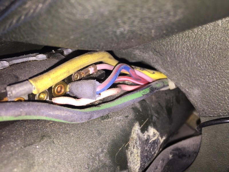
It appears I have two pink wires off the ignition. And my colored wires don’t match any schematic I have seen. This will make it difficult to follow instructions, but with help here I will figure it out.
I think I understand the concept - 12 volts to the igniter. The choices seems to be one of two ignition wires - a red/green stripe wire from the ignition to the factory tach. Or the pink wire on a standard, no tach.
As you can see from the photo, I don’t have a red/green stripe wire. That leaves the pink, which I understood was the resistor wire. And I think Bill said don’t mess with that. All you gotta do is connect the radio shack 18g 105’C wire to the igniter on one end and twelve volts out of the ignition.
So, as usual, I’m a bit confused. Also, I mentioned in the previous post having two pink wires, but I’m pretty sure one of those is a faded purple.
your twelve volt power source differs if you have a factory tach or not? With a factory tach, the connection is to the red/green stripe wire?
Without a factory tach, the connection is to the pink wire?
In every case you are looking for a wire that hot during start (starter motor turning) and run, but not hot when the key is in the accessory position. This is the wire that feeds the factory ignition system. If you have a tach, then that wire goes into, and back out of, the tach before turning into the resistance wire. You want to connect to it before it turns into the resistance wire. I like to do this behind the key switch. I don’t have a schematic for a '70 and with the key in the column this wire might be different although I thought the color code was the same. Maybe one of the guys with a '70 can chime in.
how exactly do you “connect the wire to the red/green stripe wire?
I think you maybe over thinking this. Basically you cut the wire and make a one-in, two-out, splice. You can do this with a crimp style butt connector. Or if you can get to it, and you have a tach, you could create a “Y” connection by disconnecting the bullet connector on the input side of the tach and making a Y cable using the appropriate male and female bullet connectors. While I really encourage people not use them if possible, you can use an inline splice. Never use these for anything that pulls much current. The Pertronix is passable, triggering a relay is passable, but the coil absolutely is not.
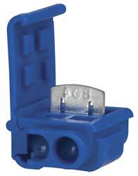
those connectors are very difficult to disconnect and reconnect.
I kind of see that as a benefit. You don’t want it to be coming loose. I think if you buy a good quality connector (3M) with a single wire involved it doesn’t seem to be an issue for me. Of course I can only think of a couple of times (when the car was parked in hotel parking overnight) that I actually used it. If you want it to be a lot easier than adding a switch would be the best option.
Is this your own method of getting 12 volts to the igniter?
Yes it is. In most cases I am interested in keeping a stock appearance. I have been installing these things well before anyone was making the kits. If I want to run a low impedence coil that pulls more current than the key switch is designed for, then I use a relay. It has been a while but when I did the article on the Rocketman kit it was as close to plug and play as you can get. All I recall adding was a connection to the starter solenoid for 12 volts constant.