Thanks Bill. The “even better” part is no flashing at the LF threshold. I understand many LF lamps were removed by dealers in order to appease owners that were annoyed by the incessant flashing as the LF threshold was reached.
But what about the charm of the flashing light? Or the hum of turn signal motors? Or the hissing of vacuum headlights? You just can’t replace nostalgia like that. :0)
I interviewed a service writer that worked at a Ford dealership when the Thunderbird came out with with this feature. He said that customers thought the cars got horrible gas mileage because of the lights. Apparently many thought that low meant empty or very close to it. The perception was that they had to fill up far more often. They would bring the car in thinking there was something wrong with it cause it was using so much gas… He also told me that the “Belts” light was a big issue as some though the car had a faulty fan belt or something. He had some great stories.
Thanks for that info on the link, Robert. I will pull the sender this winter and see where I stand on that. If it looks like I need this, I’ll be in touch.
I had also purchased one of these new 2 - wire sending units and my experience was the same as others, not very accurate.
Full tank of gas gives me a 3/4 indication and within 100 miles it’s reading “E”. I know I get lousy gas mileage but not that bad!
In an attempt to remedy this issue I purchased and installed a Techno Versions “MeterMatch” which will rescale the sending unit to drive the meter.
In theory this could work, but the bottom line is if the sending unit outputs the same resistance with 5 gallons of gas as it does with no gas (which is what I’m seeing with mine (74.6 ohms)) then no scaling device will help at the low end. The one positive about the new sending unit is that the low gas indicator does work and I use that to tell me it’s time to fill up. I just get nervous staring at the Gas gauge reading “E” even though I know it’s not correct.
But now I have the Meter Match set to indicate a full tank @ 18 ohms and 1/4 of a tank at 75 ohms and when the Gas gauge gets to 1/4 of a tank, I’ll either fill up or wait for the fuel warning light, assuming you can trust that that hasn’t failed since your last fill-up! ![]()
Follow up…
I filled the tank up with gas (even squeezed in more after the pump auto shut off) and read the sender output, it read 18.5 Ohms. I believe the sending unit should have an output range of 10 (full tank) to 75 ohms (empty tank). My next step is to remove the sending unit and verify that is indeed the case (10 - 75 ohm range) and if so the fix may be to just bend the float connecting rod down a bit to have it indicate 10 when full and hopefully 75 when empty. Right now it looks like the rod is situated such that the float is “under water” when the tank is full (because it’s hitting the mechanical top limit) and is floating in air when the tank is empty (because it’s hitting the mechanical low limit). At least that’s what I’m hoping is the case.
I’ll have to wait until I burn through at least most of my gas, and with winter approaching that may not be until spring.
Installed TechnoVersion’s MeterMatch-VR last week and it has done a lot to improve the fuel level indication within the range of the sending unit. I’m planning on a more detailed post of the broader issues and what this product was able to address. I’ve now gotten brave and ordered their TachMatch TM-02-I-Drive to calibrate my tach that now reads more than 15% too high. I’m getting way too much practice at pulling the dash and instrument cluster.
Gas Gauge Calibration issues and partial resolution with the TechnoVersion’s MeterMatch-VR calibration module and other adjustments.
This is on a 1970 Mercury Cougar XR7 with a reproduction replacement 22 gallon tank
The following are findings in the review of several fuel sensor/pickups, gas tank geometry, fuel level indicator, and the TechnoVersion’s MeterMatch-VR calibration module. Some of these may vary with other Cougar model years but are probably generally applicable for a broader range of model years.
First the geometry of the fuel tank (repro) was represented on a drawing and it was used to map out sender location, range of motion, and pickup positions to establish some of the limits of the several available fuel sensor/pickups (see list below).
Results of that review are summarized as follows:
• The fuel pickups do not go fully to the bottom of the tank. Meaning that there may be several gallons of fuel that the pick-up tube/filter can’t reach to deliver, especially when they miss the small sump provided in the tank.
• The float range of the level sensor is less than the full height of the tank. This may be split leaving un-measurable low and/or high levels in the tank. The gauge cannot report level above or below the float movement range. This is best adjusted to cover low level in the tank where error has a higher consequence.
• Floats and pickups don’t all line up with the 1/2” deep sump at the bottom of the tank
• It takes about an inch of liquid level to start the float moving
• The resistance range of the sensor may not be the 75 – 10 ohm (empty to full) range specified.
• The gauge response may not be representative of the sensor float movement (e.g. the float at top of range only reports three quarters of a tank, or mid and low range level indications are off)
Three reproduction sending units were on hand and reviewed (don’t know how representative these are of all that are available but they all had similar issues):
• A Motorcraft FG 86C clone with a 6-1/2 arm to the float centerline, a 6-1/2” float range (centerlines), a shorter pickup tube, and 83 to 18 ohm range – no source detail, came with the car
• A Stainless steel one with a 7-3/4” arm to the float centerline, a 6-3/4” float range (centerlines) and a 78 to 9 ohm range – don’t recall the source
• A Stainless steel one with a 7-3/4” arm to the float centerline, a 6-3/4” float range (centerlines) and a 76 to 15 ohm range with the low fuel sensor – this is a WCCC unit (no longer carried due to range and accuracy issues) – installed and calibrated.
Installation:
The MeterMaster-VR installation instructions were good with a few modifications. The ’70 model instrument cluster has a film circuit board and the MeterMaster’s optional isolation kit was very useful and the on-line instructions (not with the isolation kit) for it are generally good. Two modifications were made. The fiber insulator under the film needed the terminal holes enlarged slightly for the isolator shoulder to seat. I added some plastic “fender” washers to provide better insulation between the film and the ring connector on one terminal and between the two ring connectors on the other terminal. I’ve already got a number of added bullet connectors on the back of the cluster (Voltmeter substitution) and adding four more was not a desired approach. I found a four wire automotive trailer connector set at the parts store and used it for all but the ground connection. The wire colors don’t match the TechnoVersion’s documentation but the mark-ups are in my car file. Mounting the small module requires both choosing a location and providing mounting hardware. I put it on the firewall to the left of the fuse box and mounted it with a metal strip double sided taped to the module’s plastic box and a single sheet metal screw to the firewall. I left enough extra wire length to allow calibration with the module on the floor and sufficient to allow the wire connector to be accessible from above when pulling the instrument console.
Calibration:
The gas tank was emptied and refilled, a gallon at a time, to record sending unit response (resistance with an ohm meter) and calibrate the gauge with the MeterMaster. The MeterMaster seems to have a high resistance so accurate sensor readings were possible with it connected (the fuel gauge resistance is small enough that it must be disconnected to measure the sensor resistance in the factory configuration).
The float arm was bent prior to installation to let it just sit on the tank bottom. About 2 inches of tank level are above the sensor range. Mid and low level gauge accuracy was chosen as more important.
Sending unit resistance was monitored as the tank was filled. There was no change with the first two gallons (not enough to float the sensor). Only a small change was seen with the third gallon. This was selected as “zero” on the fuel gauge and calibrated accordingly. Based on the nearly two lost inches of float range at the top of the tank it was estimated that full would be around 18 gallons. The MeterMaster allows four calibration points so intermediate points were chosen evenly spaced from empty (3 gallons) and a “full” indication at 18 gallon. The fuel sensor resistance reached a minimum near 18 gallons as expected and this was calibrated as full.
Results
Due to sensor limits I don’t see the top five gallons but I have a good indication of the rest of the tank level. The gauge range is from the bottom of the red “empty” mark to the top of the range marks. I don’t have any usage experience with this yet but it appears to be very promising.
Now I need figure out why the low level warning light doesn’t work. That will be a separate post.
I have an issue with my tachometer reading more than 15% high and have ordered their TachMatch Model TM-02-I-Drive to allow me to recalibrate it. That too will be a separate post after installation.
Jayco59,
Here is my mapping of the 1970 22 gallon tank. I don’t know if the '69 is the same.
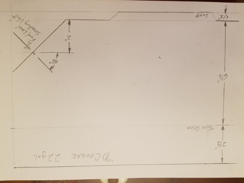
Upside down but usable.
Looks OK to me
Thanks “70XR7Tom”. My tank seems to be an 18 gallon tank, but the shape is similar.
The dimensions are probably different, since it’s 4 gallons smaller.
Upside down is perfect, that’s how I see the tank when I’m under the car! ![]()
Jay
An update to this thread. I am now rebuilding and properly calibrating the factory senders including replacing the thermistors with a much improved version. I also rebuild the non low fuel senders as well.
This link will take you to the details about what I am doing.
https://desertclassicparts.com/fuel-sending-unit-rebuilding-service/

If you want to really diagnose the problem I have also developed a gauge tester for Ford products from 1956 to 1983. This will let you test the fuel, temp, and oil pressure gauge as well as verifying the output of the Instrument Voltage Regulator.
https://desertclassicparts.com/product/gauge-tester-gt-ford-1/

Dear Sir,
I just acquired a 1983 Cougar 5.0 LS and I need a sending unit for it.
Sadly, the tank was previously removed and the sending unit is lost.
Thanks for any info.
Regards,
Azi
Tucson,AZ
520 471 7822
For an 83 Cougar, I’m guessing a sending unit for a same-year Mustang would work. Both were based on the Fox platform and the trunk floor/fuel tank arrangement is the same.
Thank you!
Any info on locating the part number?
If it is indeed the same sending unit for both the Mustang and the COugar ( 5.0 L ) then it should be p/n : E3ZZ-9275-C. It shows up on the internet in multiple places. Should be stock at numerous after-market vendors.
Good Luck.