I was looking at the option to remove the vacuum actuator and replace with the electric kit (ford Probe motors). My Engineer buddy asked me “why not linear actuators”?. So I am looking into what that entails.
Has anyone ever tried or is anyone using them???
Pros, Cons, comments???
Someone was trying to use linear actuators but there wasn’t one that was the correct length. I don’t think they went ahead and had a custom actuator made
I measured the front headlight shaft movement on my 1969 Cougar and It was pretty close to just 2 inches (50mm).
They do make such a beast, of course you’d have to fabricated some sort of bracketing and probably work out some sort of relay driving circuit off the headlight switch.
Jay
The total height of the space available doesn’t work for most linear actuator designs. You need about three inches of throw from a device that is only three inches or so tall.
If you think about it, isn’t the vacuum actuator currently used a “linear” actuator. That shaft rides up and down in a linear fashion so I don’t see why an electronically driven linear actuator wouldn’t possible fit in the same location. It certainly would be smaller width wise and I don’t see why it would be any longer than the current vacuum driven unit.
You guys really have me thinking about this design, I’m probably going to attempt to work out a system using a 2" Linear actuator using something like I mentioned in my prior post. Now I have a 69, so I only have to worry about a single center actuator, the prior years have 2 so that’s more work and cost (~ twice ).
Jay
The electrical for it can be done with 2 5 pin relays. The throw I measured was 3.25 inches of throw estimated. I plan to pull the assembly out after the holidays and mock up one to work out the mounting and motion of one. I’ll keep you posted.
I believe this is the gentleman’s blog that was mentioned above by Sebastian.
The only problem I see with the designs that use the Probe/Mazda motor is that the motors are not that cheap.
You looking at $175 to $200 from the different retailers, possibly you can get it cheaper at a local junk yard?
I suspect the prices have increased with them being repurposed for these kinds of modifications (more demand).
Ok, So I’ve made some progress with this idea…
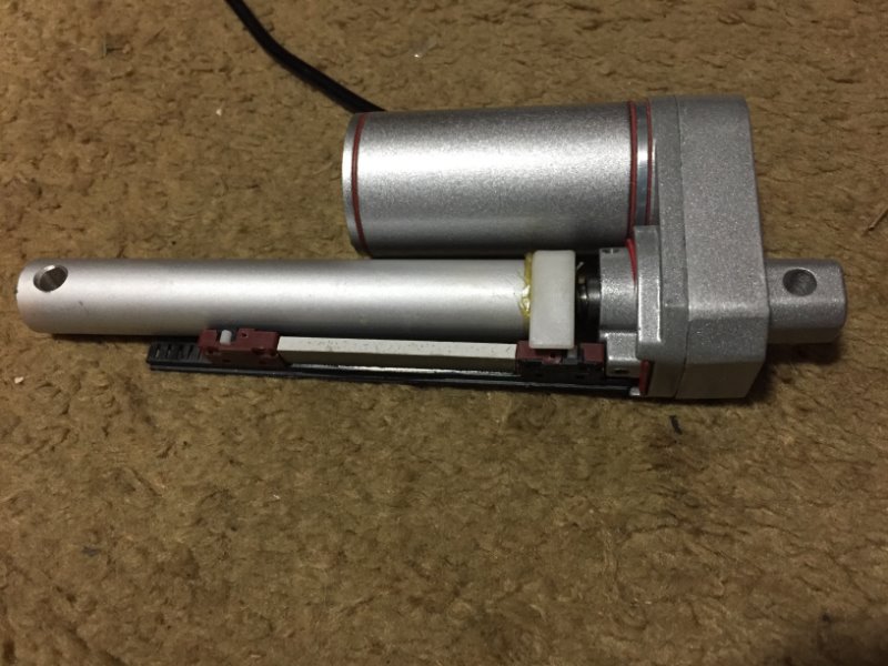
I’ve found (on order) a 3 inch linear actuator that should do the trick, auto limit switches and can handle 100+ lbs.
Measured the amount of force the current springs apply to the doors and it is ~17 or so pounds. I’m thinking my design will not use these helical springs at all, but we’ll see when I get that part going.
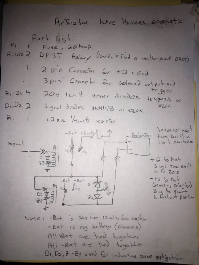
I’ve designed and built the wire harness, I’ve attached the schematic and a picture of the final prototype I built.
I designed it using 2 - SPDT relay’s as I couldn’t find a weatherproof DPDT relay, which would have simplified the design a bit.
The basic premise of the design is that the actuator needs +12 volts and ground applied to the 2 wires for full actuator extension and the wires reversed (Ground and +12 volts reversed on the actuator) to have the actuator retract.
All the diodes are for inductive spike mitigation so the relay contacts and other circuits are not affected when switching inductive (motor and relay) loads. The input signal is the light switch output (+12 when lights are on, ground when lights are off).
My EE skills are a little rusty, so if someone has any comments/suggestions to improve the circuit design, please post them.
I did test it out on a 12 VDC motor and it did spin in one direction and then the other direction when I applied 12 VDC to the input signal.
Once I get the actuator in hand, I can start on the physical workings of that. I’m currently thinking about suspending the actuator on springs to take up the extra travel of the actuator once the headlight doors reach their physical stops (before the actuator reaches it’s stops). My measurements indicate I need about a 2-1/4 inch travel, while the closest actuator I could find was 3 inches, so I need to be able to account for 3/4 of an inch between when the headlight door hits it physical limit and the actuator hits its physical limit and stops. The springs would take up that difference (at least that’s the working design). I’ll have more on that once I get my hands on some hardware. The actuator on order claims that it has a clutch on it and I’m hoping that means it will just stop extending the shaft when it hits the 2-1/4 inch limit of the door, but I’ll have to see if that’s the case. If that is the case, then I won’t have to bother with my spring design.
Jay
Note Schematic indicates DPST (Double Pole - Single Throw) relay, it’s actually a SPDT (Single Pole - Double Throw) relay.
OK, I think I following with you, with no DPDT relay you will use two relays, one open and one to close, with H/L switch as a trigger. hope you find a actuator with that you can limit travel. Keep us informed.
I am on the parallel path with you on this. Can’t wait to see how you mount the unit. Top mount on the eyelid is easy, lower I have a mock up but waiting on my actuator for final.
Felix,
I have an actuator and I have a preliminary brackets made up, but I believe I need to mount the actuator at a slight angle, not directly under the pivot point. I have some pictures of my brackets and I even have a video of the doors working. The door doesn’t close 100%, it’s close but not perfect (Yet)!
I have two issues I need to overcome; the first is the actuator has a 3" displacement and I only need 2-1/4", and the angle of the mount as I previously mentioned. The upper bracket attempts to address the extra 3/4 of an inch by having a 3/4" slot for the extra travel to be taken up by.
Jay
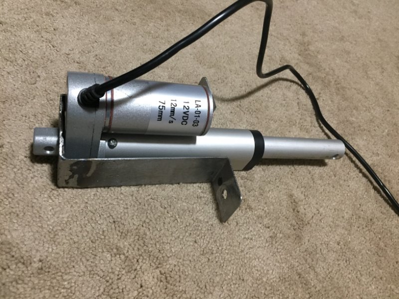
Actuator:
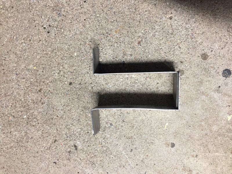
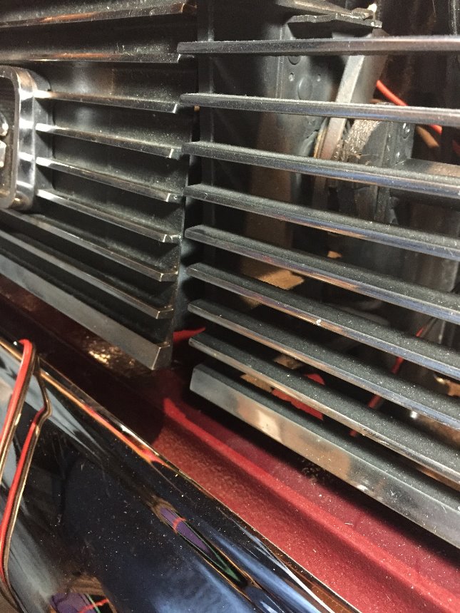
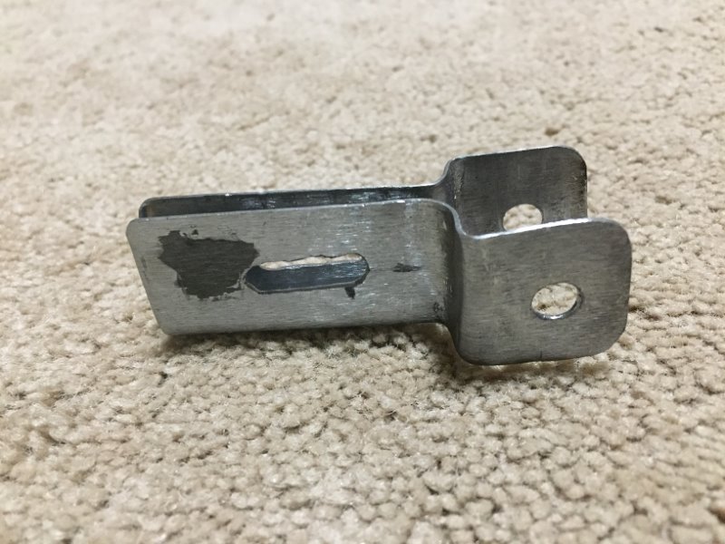
Lower Bracket for mounting the Actuator to the car (where the vacuum motor was). The bracket mounts down (actuator sits between (inside) the 2 sides) exactly where the vacuum motor was:
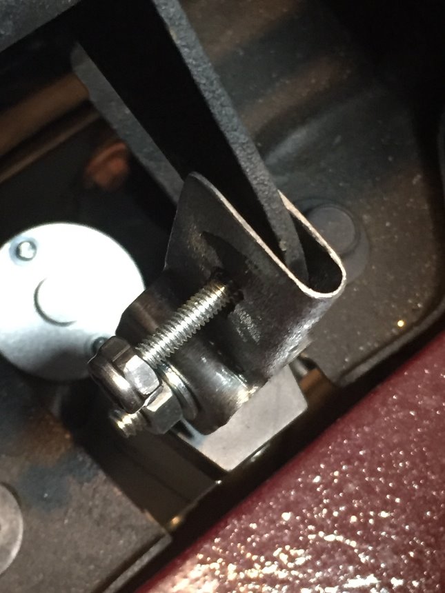
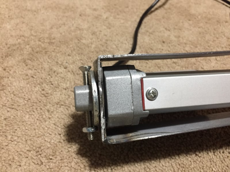
Here are some more detailed pictures. I’m trying different spacers to lower the actuator mounting position hoping that will get the door to close completely.
Tomorrow I’ll be working on it some more.
I had in mind to have the upper as swivel rather than a slot. Basically a plate with a hole at each end so it will make up the difference and allow the eyelid to move at an arch. The top of the actuator would pass the bracket just slightly and help the eyelid close all the way.
That sounds feasible, would it matter which way the plate swivels? I mean does the design allow for it to swivel in either direction, or would it be built to only allow for swivel in one direction and does that even matter?